
High-resistance polyamide based (PA) technopolymer.
Black base.
Case in the following colours:
- C2: RAL 2004 orange, glossy finish.
- C3: RAL 7035 grey, glossy finish.
- C1: RAL 7021 grey-black, glossy finish.
The ultrasonic welding between the base and the case prevents separation and avoids dust penetration.
Window
Transparent polyamide based (PA-T) technopolymer, moulded over the case and with a perfect seal. Resistant to solvents, oils, greases and other chemical agents (avoid contact with alcohol during cleaning operations).
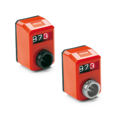
Display
It indicates the displacement of the mechanism controlled by the spindle from the start position (0).
Three-digit roller counter. The digits of red rolls show the decimal values.
The display can be in different positions (see "Table of the possible combinations").
- AN: inclined display, counter in upper position.
- AR: inclined display, counter in lower position.
- FN: front display, counter in upper position.
- FR: front display, counter in lower position.
Internal gasket
O-ring front sealing in NBR synthetic rubber, between the case and the boss.
Rear gasket
Foam polyethylene, supplied.
Standard executions
Boss with Ø 10 mm H7 reamed hole, fitting to shaft by means of a grub screw with hexagon socket and cup end, included in the supply.
- DD50: black-oxide steel boss.
- DD50-SST: AISI 303 stainless steel boss.
Direction of rotation
- D: clockwise. Increasing values with clockwise rotation of the boss.
- S: anti-clockwise. Increasing values with anti-clockwise rotation of the boss.
Weight
22 grams.
Compact roller counter, ergonomically designed digits for rapid reading. The readability of the counter is increased by the magnifying window.
Features and applications
Direct drive mechanical position indicators can be assembled on passing through spindles in any position to give direct reading of the positioning of a machine component. They are suitable also for motor driven applications (see “Table of the possible combinations").

- Drill a Ø 6 mm by 10 mm hole in the body of the machine with a 18 mm centre distance from the spindle to fit the rear referring pin.
- Set the spindle to the start or referring position.
- Fit the indicator with the zeroed roller counter onto the spindle and make sure that the referring pin fit the hole.
- Clamp the boss to the spindle by tightening the grub screw with hexagon socket and cup end, according to UNI 5929-85.
- Special readings after one revolution.
- Case in different colours.
- Completely sealed digital position indicators with IP 67 protection class, see table EN 60529 obtained by means of a brass bushing with double seal ring inside the rear cavity of the base.
- MDX-50: polyamide based (PA) technopolymer knob.
- RB50: black-oxide steel reduction sleeves.
- RB50-SST: AISI 304 stainless steel reduction sleeves.
- BSA-T50: shaft locking base in polyamide based (PA) SUPER-technopolymer, black colour, matte finish. BSA-T50 locking bases allow an easy and quick locking of the spindles after their positioning. They are equipped with a Ø 6.1 mm hole to fit the referring pin of the indicator. They can be assembled with the handle either on the right or on the left and can be fitted to the machine by means of two M3 cylindrical-head screws (not included in the supply).