
Glass-fibre reinforced polyamide based (PA) technopolymer, black colour.
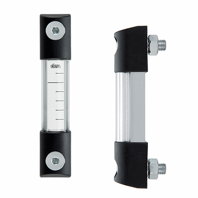
Support
Aluminium in natural colour.
Graduated contrast screen
White lacquered aluminium. It can be taken out before assembly to allow the insertion of level lines or words.
Standard executions
See configuration table.
Maximum fluid level visibility even from side positions.
Technical data
In laboratory tests carried out for a relatively limited time with the following liquids at a temperature of 23° C: mineral oil type CB68 (according to ISO 3498) for HCK, mineral oil type CB68 (according to ISO 3498) water or water/glycol-based solutions ( 50%) for HCK-GL, the resistance values were much higher than 35 bar.
Maximum continuous working temperature:
- HCK: 100°C (with oil).
- HCK-GL: 100°C (with oil, water, glycol-based solutions).
- HCK-GL-SST: 130°C (with oil, water, glycol-based solutions). In laboratory tests these indicators showed an excellent resistance to temperatures up to 150/160°C for many hours with pressures of 5/6 bar.
For use with other fluids and under different pressure and temperature conditions, please contact ELESA Technical Department.
In any case we suggest to verify the suitability of the product under the actual working conditions.
- Column level window in transparent methylmatacrylate (PMMA) for max 70°C use.
- Polyamide based technopolymer float (from HCK.127) red colour.
- NBR float (from HCK.176) black colour with AISI 316 stainless steel spiral for special executions, viscous liquids, high temperatures.
- Indicators with level visibility (e) up to 1444 mm and fixing holes with hole centre distance (f) up to 1.500 mm.
- Packing rings in special material depending on the customer's needs.
- Built-in thermometer with red indication line (from HCK.127).
- External scale thermometer (Fig. 1) with probe in direct contact with the fluid.
- Special screw with nickel-plated brass tap (Fig. 3) to be fitted to the lower assembly end for any maintenance operation requiring the indicator exclusion.
Accessories on request (to be ordered separately)
SLCK electric level sensor (Fig.2, from HCK.127) can be fitted, as needed, along the axis of the indicator with right (DX) or left (SX) connectors, normally closed (NC) or normally open (NO) contacts.