
SFC.
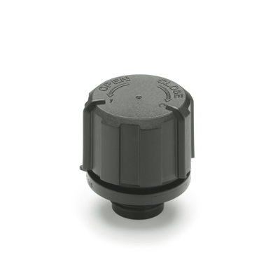
Breather caps
Velg deltype
Velg ønsket deltype for å se forhåndsvist tegning av tekniske dimensjoner

Bracket Material
Material
Bushing Material
Carrying Capacity
Diameter
Plunger Diameter
Type Of Assembly
Type Of Tube
Diameter Bases
Connecting Thread
External Diameter
Handle
Hole
Lever Length
Wheel Base
Threaded Screw
Hole Distance
Threaded Connection
Type Of Bellow
Type Of Vacuum Cups Holder
Vacuum Cup Holders Dimension
Vacuum Cups Dimension
Connector
Main specifications
Material
- Cover: polyamide based (PA) technopolymer, black colour, semi-matte finish.
- Threaded connector: acetal based technopolymer (POM), black colour, semi-matte finish.
Packing rings
NBR synthetic rubber O-Ring.
Air filter
Polyurethane foam mesh "tech-foam" (polyester base), air filtration 10 µ.
Maximum continuous working temperature
80°C.
General information
Features and applications
The cover of the SFC. breather cap (ELESA Patent) can be positioned in two different ways:
- Breather position: air is let in and out of the reservoir in normal conditions of use.
- Closure position: a packing ring between the cover and the threaded connector flange guarantees a perfect sealing of gas or liquid contained in the reservoir.
Other executions
Special executions on request
- Air filter in polyurethane foam mesh "tech-foam" (polyester base) with air filtration 40 µ.
- Cover in RAL 2004 orange.
Instructions of use
Assembly instructions
The components are supplied not assembled.
- Screw the threaded connector by means of a hexagon socket, tightening torque 8 Nm (fig. 1).
- Insert the "tech-foam" filter in its proper upper housing.
- Fit the cover on the threaded connector by properly matching the two different teeth (one large and one tight) inside the cover, with the relevant knurlings on the upper part of the threaded connector (fig. 2).
- By turning the cover clockwise of a few degrees the breather position is reached: the index on the cover marked with 1 is in line with the index of the threaded connector (fig. 3).
- By further turning the cover clockwise following the CLOSE arrow, the closure position is reached: the index on the cover marked with 0 is in line with the index of the threaded connector (fig. 4).
- To reach from the closure position to the breather one just turn the cover anticlockwise following the OPEN arrow until the click.
- By further turning the cover anticlockwise following the OPEN arrow, it is possible to remove the cover from the threaded connector, thus allowing the operator to clean the two components or to substitute or clean the "tech-foam" filter (fig. 5).