Velg deltype
Velg ønsket deltype for å se forhåndsvist tegning av tekniske dimensjoner
ADT(0) ALL.C(0) ALL.I(0) ALL.LM(0) ALL.LS(0) ALL.PB(0) ANPS(0) APC(0) AVC-4(0) AVC-6(0) AVC-8(0) AVF-A(0) AVF-SH(0) AVG(0) AVM(0) AVR-Q(0) AVR-R(0) BAG2-120(0) BAG2-180(0) BAS2(0) BAS3(0) BASE - LV.FO-LV.FO-AS(0) BASE LS.A-PP - LV.F-PP(0) BASE LS.A-VD-PP - LV.F-VD-PP(0) BASE LS.VA(0) BASE LV.A - LV.A-AS(0) BASE LV.A-ESD-C(0) BASE LV.F - LV.F-AS(0) BASE LV.F-ESD(0) BDG(0) BEL-AD(0) BEL-AP(0) BEL-BH(0) BEL-MB-AV(0) BEL-MB-JV(0) BEL-MF(0) BEL-MS(0) BEL-PH(0) BEL-PM(0) BEL-RB-AV(0) BEL-RB-JV(0) BJT-p(0) BJT.(0) BL.366(0) BL.368(0) BL.666(0) BL.668(0) BM.193-SST(0) BM.193-SST-p(0) BMS(0) BMST(0) BOCK-SST(0) BOCK.(0) BOL-MB-AV(0) BOL-MB-JV(0) BOL-MF(0) BOL-PH(0) BPS(0) BPS-spacers(0) BS51(0) BS52R(0) BSA-T50(0) BSA51(0) BSA52(0) BSA52-E(0) BT-HP-SST-p(0) BT.p-HP(0) C.AT-1000_2(0) CA.VCT(0) CAR.(0) CC-MSR(0) CFA.(0) CFA/F(0) CFA/SL(0) CFA+ERS(0) CFAM(0) CFAX-B-IP(0) CFAX-p-IP(0) CFAX.(0) CFB.(0) CFBS(0) CFC.(0) CFD.(0) CFDA(0) CFE.(0) CFF.(0) CFG-ERS.(0) CFG.(0) CFGY-D(0) CFGY-S(0) CFH.(0) CFI.(0) CFJ-AE-V0-B(0) CFJ-AE-V0-p(0) CFJ.(0) CFK(0) CFL(0) CFM-AE-V0(0) CFM-CH(0) CFM-CLEAN(0) CFM-L-A(0) CFM-L-B(0) CFM-MD(0) CFM-p(0) CFM-p-CH(0) CFM-p-SH(0) CFM-SH(0) CFM-SL(0) CFM-TR-A(0) CFM-TR-B(0) CFM-TR-G(0) CFM-TR-SST(0) CFM-VD(0) CFMQ(0) CFMQ-AE-V0(0) CFMR(0) CFMW(0) CFMW-AE-V0(0) CFMX-CH(0) CFMX-SH(0) CFMY(0) CFMY-NL-M-D(0) CFMY-NL-M-S(0) CFMY-NL-T-D(0) CFMY-NL-T-S(0) CFN.(0) CFNR-B-D(0) CFNR-B-p-D(0) CFNR-B-p-S(0) CFNR-B-S(0) CFNR-p-B-D(0) CFNR-p-B-S(0) CFNR-p-D(0) CFNR-p-S(0) CFO.(0) CFP.(0) CFQ.(0) CFR.(0) CFSQ.(0) CFSW(0) CFT.(0) CFTX-PP(0) CFTX.(0) CFU-RA(0) CFU.(0) CFV.(0) CFVT(0) CHG(0) CKE.(0) CLC.(0) CLT.(0) CM.(0) CM/L(0) CMC(0) CMD.AL(0) CMDX-AL(0) CMLX(0) CMM.(0) CMM.AL(0) CMM.BL(0) CMM.SST(0) CMMR-NC(0) CMMR-NO(0) CMMY(0) CMN(0) CMS(0) CMS-CLEAN(0) CMT.AE-V0(0) CMUF(0) CMUF-A4(0) CMUF-AH(0) CMUM(0) CMVT-A2(0) CMVT-C2(0) CMZ.(0) CP-XX(0) CQ.(0) CQ.SST(0) CQT.AE-V0(0) CQT.FM(0) CQTF.FM-AE-V0 _ 1(0) CQTL.FM(0) CS-RPR.(0) CS.(0) CS.SST(0) CSF(0) CSL.FM(0) CSM(0) CSMH(0) CSMT-A(0) CSTM.(0) CT-FG(0) CT-FG-p(0) CT-FG-SST-p(0) CT-S(0) CT-S-2A(0) CT-S-A(0) CV-T(0) CV-T-2A(0) CV-T-2P(0) CV-T-A-P(0) CV-T-P(0) CWL(0) CWQ(0) CX.(0) DD50(0) DD51(0) DD51-E(0) DD51-E-RF(0) DD52R(0) DD52R-E(0) DD52R-E-RF(0) DE51(0) DIN 172(0) DIN 179(0) DIN 39(0) DIN 444(0) DIN 444-NI(0) DIN 466-A4(0) DIN 466-ZB(0) DIN 468(0) DIN 508(0) DIN 508-NI(0) DIN 580(0) DIN 6311(0) DIN 6319(0) DIN 6319-A4(0) DIN 6319-NI(0) DIN 6321(0) DIN 6332(0) DIN 6335(0) DIN 6336(0) DIN 653-ZB(0) DIN 950-A(0) DIN 950-D(0) DIN 98(0) DS-EBP.(0) DS-EMPC(0) DS-ETH(0) DS-M.1043(0) DVA 1(0) DVA 2(0) DVA 3(0) DVA 4(0) DVA 5(0) DVA 6(0) DVA 7(0) DVB.6(0) DVB.7(0) DVC.1(0) DVC.2(0) DVC.3(0) DVE-A(0) DVE-B(0) DVF.6 SST(0) DVF.7(0) DVG(0) DVI(0) DVL.1(0) DVL.1-SST(0) DVL.2(0) DVL.2-SST(0) DVL.3(0) EBK-B-SOFT(0) EBK-C SOFT(0) EBK-H SOFT(0) EBK-p-SOFT(0) EBK-x(0) EBP-B(0) EBP-CH(0) EBP-L(0) EBP-L-CLEAN(0) EBP.(0) EBP.FLX(0) EBP.SAN(0) EBR(0) EBR-CH(0) EBR-PN(0) EBR-SW(0) EBR-SWB(0) EBS+x(0) EBS+x SOFT(0) ECA-IZN.381(0) ECA.B(0) ECA.B SAN(0) ECA.M(0) ECA.P(0) ECA.T(0) ECA.V(0) ECA.W(0) ECA.W SAN(0) ECB.D(0) ECB.G(0) ECB.I(0) ECB.T(0) ECBF.T(0) ECM.K(0) ECO.R(0) ECO.S(0) ECS.T(0) EFH.620(0) EFH.620-SST(0) EGH.SOFT(0) EGK.SOFT(0) EIK.(0) EKH.(0) EKK-B(0) EKK-p(0) EKK-SST-MD(0) EKK-SST-SAN(0) EKK-SST-VD(0) ELC-FC3(0) ELC.(0) ELCK-1(0) ELCK-2(0) ELCR.(0) EMPC(0) EMW+IEL(0) EMW+IR(0) EPR-PF(0) EPR-PF-IP(0) EPR-SH(0) EPR/F-SH(0) ERB-PF(0) ERB.(0) ERFW+I(0) ERZ-SST-p-SAN(0) ESC(0) ESN.(0) ESP.(0) ETH-AN(0) ETH-CLEAN(0) ETH-EP(0) ETK.(0) ETW.375+IEL(0) ETW.375+IR(0) EVH(0) EVH-CLEAN(0) EWN-B-RC(0) EWN-p-RC(0) EWN-SST-p-RC(0) EWN-SST-RC(0) EWP.(0) EYK.(0) F.N(0) FC-M12x1(0) FC-MPI(0) FC-UC(0) FHF(0) FHS(0) FHT-C(0) FJT.(0) GA01 - GA02 - GA05(0) GA11 - GA12(0) GC.(0) GCA 2 RC(0) GCA 2 RS(0) GCA 2 RT(0) GCA 4 RC(0) GCA 4 RS(0) GCA 4 RT(0) GFL-p(0) GLA 1 RC(0) GLA 1 RS(0) GLA 1 RT(0) GLA 2 RC(0) GLA 2 RS(0) GLA 2 RT(0) GLB 1 RC(0) GLB 1 RS(0) GLB 1 RT(0) GLB 2 RC(0) GLB 2 RS(0) GLB 2 RT(0) GLC(0) GLD-AZ(0) GLD-SST(0) GLP-12(0) GLP-32(0) GLP-HT(0) GLR(0) GLS(0) GLT(0) GM.A(0) GN 000.5(0) GN 1024 D(0) GN 1024 E(0) GN 111(0) GN 111.2(0) GN 111.6(0) GN 111.8-A(0) GN 111.8-B(0) GN 111.8-C(0) GN 112.1(0) GN 113.1(0) GN 113.10(0) GN 113.11(0) GN 113.12(0) GN 113.3(0) GN 113.30-L(0) GN 113.30-M(0) GN 113.30-T(0) GN 113.5(0) GN 113.6(0) GN 113.7(0) GN 113.8(0) GN 113.9(0) GN 1130 NI(0) GN 1130 ST(0) GN 1132(0) GN 1133(0) GN 1133-NI(0) GN 1135-NI(0) GN 1135-ST(0) GN 114.2(0) GN 114.3(0) GN 114.6(0) GN 115(0) GN 115.10(0) GN 1150 VH(0) GN 1150-FH(0) GN 119(0) GN 119.3(0) GN 123(0) GN 124-INOX(0) GN 124.1(0) GN 124.3(0) GN 127 A4 B(0) GN 127 A4 H(0) GN 127 A4 HB(0) GN 127 B(0) GN 127 H(0) GN 127 HB(0) GN 132.15-A(0) GN 132.15-B(0) GN 132.25-A(0) GN 132.25-B(0) GN 133.1-B(0) GN 133.1-G(0) GN 133.2-B(0) GN 133.2-G(0) GN 134.2(0) GN 136-A(0) GN 136-B(0) GN 136-C(0) GN 1366-A(0) GN 1366-S(0) GN 138(0) GN 146.13-B(0) GN 146.13-G(0) GN 146.15-A(0) GN 146.15-B(0) GN 146.16-A(0) GN 146.16-B(0) GN 1582-MT-E(0) GN 1582-MT-H(0) GN 1582-PL-E(0) GN 1582-PL-H(0) GN 162.8(0) GN 163.15(0) GN 164(0) GN 17-SK(0) GN 17-TK(0) GN 17-VK(0) GN 17-W(0) GN 172.1(0) GN 179.1(0) GN 18-SK(0) GN 18-TK(0) GN 181(0) GN 183(0) GN 184(0) GN 184.5 INOX(0) GN 185(0) GN 187.1(0) GN 187.2(0) GN 187.4(0) GN 187.4-NI(0) GN 187.5-A-NI(0) GN 187.5-B-NI(0) GN 187.5-C-NI(0) GN 187.5-DH-NI(0) GN 187.5-E-NI(0) GN 187.6(0) GN 187.6-K(0) GN 187.6-S(0) GN 188 A NI(0) GN 188 B NI(0) GN 188 C NI(0) GN 19(0) GN 192.15-A(0) GN 192.15-B(0) GN 198(0) GN 20.1(0) GN 200-A(0) GN 200-A-NI(0) GN 200-B(0) GN 214.2(0) GN 214.3(0) GN 214.6(0) GN 215(0) GN 224.1(0) GN 224.5(0) GN 227.1(0) GN 227.2-A(0) GN 227.2-D(0) GN 227.4(0) GN 227.7(0) GN 228(0) GN 228-A4-A(0) GN 228-A4-D(0) GN 2342-B-1(0) GN 2342-B-2(0) GN 2342-E-1(0) GN 2342-E-2(0) GN 2342-L-1(0) GN 2344(0) GN 2376(0) GN 238(0) GN 249(0) GN 249.1(0) GN 250(0) GN 251.6(0) GN 252(0) GN 252.5(0) GN 264(0) GN 268(0) GN 269(0) GN 274.4(0) GN 275.4(0) GN 276.4(0) GN 277.1(0) GN 277.4(0) GN 278.1-AV(0) GN 278.1-IV(0) GN 278.1-MZ(0) GN 278.1-OZ(0) GN 278.4(0) GN 289(0) GN 291(0) GN 291.1(0) GN 292(0) GN 295(0) GN 297(0) GN 298(0) GN 302.2 (d1-l2)(0) GN 302.2 (d1)(0) GN 311(0) GN 314(0) GN 314-SU(0) GN 315(0) GN 315.1(0) GN 316-K(0) GN 316-M(0) GN 316-SK(0) GN 321-A(0) GN 321-R(0) GN 322-A(0) GN 322-R(0) GN 322.3(0) GN 328-A(0) GN 328-B(0) GN 328.5-A(0) GN 328.5-B(0) GN 333(0) GN 333.1(0) GN 333.3(0) GN 333.5(0) GN 333.6(0) GN 333.7(0) GN 334(0) GN 334.1(0) GN 335-A(0) GN 335-B(0) GN 338(0) GN 346(0) GN 347(0) GN 349(0) GN 350.3 & INOX(0) GN 355(0) GN 355.1(0) GN 355.2(0) GN 36(0) GN 36.1(0) GN 360-A-NI(0) GN 360-A-ST(0) GN 360-B-NI(0) GN 360-B-ST(0) GN 3664 (d2)(0) GN 3664 (d3)(0) GN 3664 (d4-l)(0) GN 369(0) GN 369.5(0) GN 37-A(0) GN 37-B(0) GN 37-C(0) GN 37.1-A(0) GN 37.1-B(0) GN 37.1-C(0) GN 374(0) GN 391(0) GN 391-NI(0) GN 3971(0) GN 3975(0) GN 408.1-b(0) GN 408.1-G(0) GN 408.1-K(0) GN 412(0) GN 412.1(0) GN 412.2(0) GN 412.3(0) GN 412.4(0) GN 412.5(0) GN 413(0) GN 414(0) GN 414.1(0) GN 415-A1(0) GN 415-A2(0) GN 415-B1(0) GN 415-B2(0) GN 415-B3(0) GN 415-B4(0) GN 416 L1(0) GN 416 R1(0) GN 416 S(0) GN 416.1(0) GN 417(0) GN 417-A-NI(0) GN 417-B-NI(0) GN 417-C-NI(0) GN 417-D-NI(0) GN 417.1(0) GN 424.1(0) GN 424.5(0) GN 425(0) GN 425 6(0) GN 425-A4(0) GN 425-NI(0) GN 425.1(0) GN 425.3(0) GN 425.8(0) GN 426(0) GN 426-SMA(0) GN 426.1(0) GN 426.3(0) GN 426.5(0) GN 426.6(0) GN 427(0) GN 428-A(0) GN 428-B(0) GN 429(0) GN 430(0) GN 430.1(0) GN 435(0) GN 435.3(0) GN 436-M(0) GN 436-N(0) GN 436.1(0) GN 436.1-B(0) GN 436.1-S(0) GN 444.2(0) GN 4490(0) GN 464.1(0) GN 471-GN 471.1(0) GN 472.3(0) GN 472.5(0) GN 481(0) GN 505(0) GN 505.4(0) GN 505.5(0) GN 506(0) GN 506.1(0) GN 506.2(0) GN 5063(0) GN 507(0) GN 508.1(0) GN 508.2(0) GN 509(0) GN 509.1(0) GN 509.3(0) GN 509.4(0) GN 511(0) GN 511.1(0) GN 513(0) GN 514(0) GN 514-A4 (A)(0) GN 514-A4 (AK)(0) GN 5334.13-A-d2(0) GN 5334.13-A-d2-l(0) GN 5334.13-H-d2(0) GN 5334.13-H-d2-l(0) GN 5334.13-K-d2(0) GN 5334.13-K-d2-l(0) GN 5335(0) GN 5335.4(0) GN 5435(0) GN 5445(0) GN 551.1(0) GN 558(0) GN 559(0) GN 565(0) GN 565-SMA(0) GN 565.1(0) GN 565.2(0) GN 565.3(0) GN 565.4(0) GN 565.5(0) GN 565.7(0) GN 565.9(0) GN 598(0) GN 605(0) GN 605 NI(0) GN 607(0) GN 607-NI(0) GN 607.1(0) GN 607.1-NI(0) GN 607.2(0) GN 607.3(0) GN 607.4(0) GN 607.5(0) GN 608(0) GN 608.1(0) GN 608.5(0) GN 608.6(0) GN 609(0) GN 609.5(0) GN 611(0) GN 612(0) GN 612-NI(0) GN 612.1(0) GN 612.10(0) GN 612.2(0) GN 612.3(0) GN 612.8(0) GN 612.9(0) GN 613(0) GN 613-NI(0) GN 614(0) GN 614-NI(0) GN 614.1(0) GN 614.2(0) GN 614.3(0) GN 614.4-KU(0) GN 614.4-NI(0) GN 614.5(0) GN 614.6(0) GN 614.7(0) GN 614.8(0) GN 615(0) GN 615-NI(0) GN 615.1(0) GN 615.1-NI(0) GN 615.2(0) GN 615.3(0) GN 615.3-NI(0) GN 615.4 B-BS(0) GN 615.4 BN-BSN(0) GN 615.5(0) GN 615.7(0) GN 615.8(0) GN 615.9(0) GN 616(0) GN 616-NI(0) GN 616.1-S(0) GN 616.1-SN(0) GN 616.1-SS(0) GN 617(0) GN 617-NI-INOX(0) GN 617.1(0) GN 617.1-NI(0) GN 618(0) GN 6220-A(0) GN 6220-B(0) GN 6226-A1(0) GN 6226-A2(0) GN 6226-A3(0) GN 631(0) GN 631.5(0) GN 6311.1(0) GN 6311.3(0) GN 6311.4(0) GN 6311.5-G(0) GN 6311.5-N(0) GN 6311.5-R(0) GN 6311.6-G(0) GN 6311.6-N(0) GN 6311.6-R(0) GN 6319.1(0) GN 632.1(0) GN 632.5(0) GN 6322(0) GN 6335 D(0) GN 6335 E(0) GN 6335.5-A4P(0) GN 6335.5-AM(0) GN 6335.5-AP(0) GN 6335.5-ES(0) GN 6335.5-SK(0) GN 6335.5-ST(0) GN 6335.5-TE(0) GN 6336-D(0) GN 6336-E(0) GN 6336.5-A4P(0) GN 6336.5-AM(0) GN 6336.5-AP(0) GN 6336.5-ES(0) GN 6336.5-SK(0) GN 6336.5-ST(0) GN 6336.5-TE(0) GN 6339(0) GN 6342(0) GN 6343(0) GN 665(0) GN 666 4(0) GN 668-A(0) GN 668-B(0) GN 669(0) GN 676.5(0) GN 700(0) GN 7017 B NI(0) GN 7017 B ST(0) GN 7017 C NI(0) GN 7017 C ST(0) GN 702(0) GN 704(0) GN 705(0) GN 705-NI(0) GN 706.2(0) GN 706.3 NI(0) GN 706.3 ST(0) GN 7062.1-A(0) GN 7062.1-B(0) GN 7062.10(0) GN 7062.2-A(0) GN 7062.2-B(0) GN 7062.2-C(0) GN 7062.3(0) GN 7062.30(0) GN 707.2(0) GN 7072.1-A(0) GN 7072.1-B(0) GN 7072.2-A(0) GN 7072.2-B(0) GN 7072.2-C(0) GN 7072.3(0) GN 7072.30(0) GN 709.1-B(0) GN 709.1-BR(0) GN 709.1-R(0) GN 709.1-RH(0) GN 709.1-RR(0) GN 709.1-RRH(0) GN 709.15-B(0) GN 709.15-BR(0) GN 709.15-RH(0) GN 709.15-RRH(0) GN 709.2-B(0) GN 709.2-BR(0) GN 709.2-R(0) GN 709.2-RR(0) GN 709.25-B(0) GN 709.25-BR(0) GN 709.3-B(0) GN 709.3-BR(0) GN 709.3-R(0) GN 709.3-RR(0) GN 709.35-B(0) GN 709.35-BR(0) GN 709.7(0) GN 709.8(0) GN 712(0) GN 712.1(0) GN 715(0) GN 715.2(0) GN 717(0) GN 717-C(0) GN 717-C-NI(0) GN 717-D-NI(0) GN 717-D-ST(0) GN 717-NI(0) GN 720(0) GN 721 LA(0) GN 721 LB(0) GN 721 RA(0) GN 721 RB(0) GN 721.1 LA(0) GN 721.1 LB(0) GN 721.1 RA(0) GN 721.1 RB(0) GN 721.5 LA(0) GN 721.5 LB(0) GN 721.5 RA(0) GN 721.5 RB(0) GN 721.6 LA(0) GN 721.6 LB(0) GN 721.6 RA(0) GN 721.6 RB(0) GN 722.1(0) GN 722.2(0) GN 722.3(0) GN 722.4-A-ST(0) GN 722.4-AU-ST(0) GN 722.5-A-A4(0) GN 722.5-A-SW(0) GN 722.5-A-ZB(0) GN 722.6-A-A4(0) GN 722.6-A-SW(0) GN 722.6-A-ZB(0) GN 723.3(0) GN 723.4-M(0) GN 723.4-N(0) GN 723.4-S(0) GN 7231-L(0) GN 7231-R(0) GN 7233-L(0) GN 7233-R(0) GN 7237(0) GN 7241(0) GN 7243(0) GN 7247.2(0) GN 7247.4(0) GN 7247.6(0) GN 726-M(0) GN 726-N(0) GN 726.1-A(0) GN 726.1-B(0) GN 726.1-S(0) GN 726.2-A(0) GN 726.2-B(0) GN 726.2-S(0) GN 727(0) GN 728-A(0) GN 728-B(0) GN 728.5-A(0) GN 728.5-B(0) GN 729(0) GN 730(0) GN 730.5(0) GN 732(0) GN 732.1(0) GN 7330-A(0) GN 7330-C(0) GN 7332-A-EP(0) GN 7332-A-GS(0) GN 7332-C-EP(0) GN 7332-C-GS(0) GN 7336.7(0) GN 7336.8(0) GN 736(0) GN 736.1(0) GN 742.5-A(0) GN 742.5-E(0) GN 742.5-O(0) GN 743.10-AK(0) GN 743.10-AN(0) GN 743.10-B(0) GN 7430(0) GN 7440-A-2(0) GN 7440-A-3(0) GN 75(0) GN 75.5(0) GN 75.6 D(0) GN 75.6 E(0) GN 750(0) GN 798(0) GN 798.1(0) GN 798.4(0) GN 815(0) GN 815-NI(0) GN 815.1-NI(0) GN 815.1-ST(0) GN 816(0) GN 816-10(0) GN 816.1(0) GN 816.1-10(0) GN 817(0) GN 817-C(0) GN 817-C-NI(0) GN 817-NI(0) GN 817.1(0) GN 817.2(0) GN 817.2-NI(0) GN 817.3(0) GN 817.3-C(0) GN 817.4(0) GN 817.4-NI(0) GN 817.5(0) GN 817.6 EC(0) GN 817.6-EB(0) GN 817.7-A(0) GN 817.7-D(0) GN 817.7-E(0) GN 817.8(0) GN 817.9(0) GN 8170(0) GN 8170-FH(0) GN 818-B(0) GN 818-BK(0) GN 818-BKN(0) GN 818-BN(0) GN 818-C(0) GN 818-CK(0) GN 818-CKN(0) GN 818-CN(0) GN 822(0) GN 822-NI(0) GN 822.1_ni(0) GN 822.1_st(0) GN 822.6(0) GN 822.7(0) GN 822.8(0) GN 822.9 B(0) GN 822.9 BN(0) GN 822.9 C(0) GN 822.9 CN(0) GN 826(0) GN 827(0) GN 827.1(0) GN 828(0) GN 828-UA(0) GN 828-UB(0) GN 8341(0) GN 8350(0) GN 911(0) GN 911.3(0) GN 912.2(0) GN 913.2(0) GN 913.3(0) GN 913.5-INOX(0) GN 913.6(0) GN 918(0) GN 918.5-NI(0) GN 919(0) GN 923-A(0) GN 923-K-A(0) GN 923-K-R(0) GN 923-R(0) GN 923.3(0) GN 923.7(0) GN 924-A(0) GN 924-R(0) GN 924.3(0) GN 924.7(0) GN 927.2-A (d1)(0) GN 927.2-A (d2-l2)(0) GN 927.2-B (d1)(0) GN 927.2-B (d2-l2)(0) GN 928(0) GN 928.1(0) GN 933.5(0) GN 936-SCL(0) GN 936-SL(0) GN 936-SUL(0) GN 938.1(0) GN 939-E(0) GN 939-EB(0) GN 939-F(0) GN 939-FA(0) GN 949-A(0) GN 949-D(0) GN 950.6-A(0) GN 950.6-F(0) GN 957(0) GN 965-A(0) GN 965-B(0) GN 965-C(0) GN 965-D(0) GN 968-A(0) GN 968-B(0) GN 968-C(0) GN 968-D(0) GN 970-ALM-A(0) GN 970-ALM-B(0) GN 970-ALM-C(0) GN 970-STB-A(0) GN 970-STB-B(0) GN 970-STB-C(0) GN 990 D(0) GN 990 V(0) GN 991(0) GN 992(0) GN_425_9_A(0) GN_425_9_B(0) GN_425_9_C(0) GR-M.1043(0) GRM.1043/30(0) GW12(0) HCFE-EX(0) HCK-PP(0) HCK-ST - HCK-STL(0) HCV-E-ST(0) HCX-AR(0) HFTX-HT-FKM(0) HGFT-HT-PR(0) HGFT. EX(0) HRT-T(0) I.126(0) I.126-p(0) I.135(0) I.137(0) I.142(0) I.147(0) I.149(0) I.150(0) I.167 p(0) I.168 SOFT(0) I.195(0) I.218(0) I.222(0) I.222-N(0) I.229+x(0) I.280(0) I.280-p(0) I.281(0) I.281+x(0) I.281+x sst(0) I.281+x+Gh(0) I.301+x(0) I.301+x SST(0) I.307(0) I.481+x(0) I.580 N(0) I.601+x(0) I.601+x-SST(0) I.618-B-SOFT(0) I.618-N-SOFT(0) I.621+Gx(0) I.621+x(0) I.621+x-SST(0) I.622(0) I.622 N(0) I.622-N-CLEAN(0) I.631+x(0) I.644(0) I.680 SOFT(0) I.701+x(0) I.731+x(0) I.741+x(0) I.780(0) I.780-MD(0) I.780-N(0) I.780-SAN(0) I.780-VD(0) I.780+x(0) IEL.N SOFT(0) IEL.N-H-SOFT(0) IEL+x SOFT(0) IF(0) IFF(0) IGF(0) IH.N(0) IR.302(0) IR.302-SST(0) IR.407(0) IR.407-SST(0) IR.612(0) IR.612-SST(0) IR.620(0) IR.780(0) IRS.802(0) IRS.802-SST(0) IRS.820(0) ISO 7379(0) IZN-XX(0) IZN.380(0) IZN.380+FGS(0) IZN.380+K(0) IZN.381(0) IZN.381+FGS(0) IZN.381+K(0) IZP.(0) IZP+GS(0) IZP+K(0) L.152(0) L.652-B(0) L.652-p(0) L.652-S-B(0) L.652-S-p(0) L.652-X-B(0) L.652-X-p(0) L.652M(0) LAC-FL-F-SST(0) LAC-FL-O-SST(0) LBR-A(0) LBR-N(0) LM-HD-SST(0) LM.(0) LM.AC(0) LM.F-HD-SST(0) LM.SST(0) LM.SST-AC(0) LM.SST-TR(0) LM.SV(0) LM.TR(0) LMD.F-2SL (d-l)(0) LMD.F-2SL (d)(0) LMD.F-2SL-SST (d-l)(0) LMD.F-2SL-SST (d)(0) LMD.F-2SL-SST-TV (d-l)(0) LMD.F-2SL-SST-TV (d)(0) LMD.F-2SL-TV (d-l)(0) LMD.F-2SL-TV (d)(0) LMD.F-SL (d-l)(0) LMD.F-SL (d2)(0) LMD.F-SL-SST (d-l)(0) LMD.F-SL-SST (d2)(0) LMD.F-SL-SST-TV (d2)(0) LMD.F-SL-TV (d-l)(0) LMD.F-SL-TV (d2)(0) LMD.F-SL-TV-SST (d-l)-d(0) LMP(0) LMP.B-TR(0) LMP.B-TV(0) LMP.F B(0) LMP.F B-TR(0) LMP.F B-TV(0) LMP.F P(0) LMP.F P-TR(0) LMP.F P-TV(0) LMP.FF(0) LMP.FF d l(0) LMP.p(0) LMP.p-TR(0) LMP.p-TV(0) LMP.SST FF dl(0) LMP.SST-FF(0) LMR.(0) LMR. B(0) LMR.F(0) LMR.F B(0) LMR.F-SST(0) LMRS.(0) LMTF(0) LMY -HS(0) LMY-EH(0) LMY-HV(0) LMY.B(0) LMY.F-B(0) LMY.F-EH(0) LMY.F-HS(0) LMY.F-HV(0) LMY.F-P(0) LMY.P(0) LPR(0) LS.A(0) LS.A - LS.A-AS(0) LS.A-AS+SJF(0) LS.A-PP-SST(0) LS.A-SST(0) LS.A-SST-VD(0) LS.A-STP(0) LS.A+SJF(0) LS.VA(0) LS.VA-SST(0) LS.VA-STP(0) LSQ.A-SST(0) LSQ.A-SST-VD(0) LSQ.VA-SST(0) LSX.A(0) LV.A(0) LV.A-125-ACV & LV.A-125-ACV-AS(0) LV.A-125-APS & LV.A-125-APS-AS(0) LV.A-AS+SJF(0) LV.A-ELK(0) LV.A-ESD-C(0) LV.A-SST(0) LV.A-SST-ESD-C(0) LV.A-SST-VD(0) LV.A-STP(0) LV.A+SJF(0) LV.F(0) LV.F-125-ACV & LV.F-125-ACV-AS(0) LV.F-125-APS & LV.F-125-APS-AS(0) LV.F-AS+SJF(0) LV.F-ESD-C(0) LV.F-PP-SST(0) LV.F-SST(0) LV.F-SST-VD(0) LV.F-STP(0) LV.F+SJF(0) LV.FO(0) LV.FO-AS(0) LV.FO-AS+SJF(0) LV.FO-STP(0) LV.FO+SJF(0) LVQ.A-SST(0) LVQ.A-SST-VD(0) LVQ.F-SST(0) LVQ.F-SST-VD(0) LVQ.FO-AS-SST(0) LVQ.FO-SST(0) LW.A(0) LX(0) LX-AS(0) LX-HS(0) M.1043-AN(0) M.1043-BM-AN(0) M.1043-BM-EP(0) M.1043-BM-SST(0) M.1043-EP(0) M.1043-SCM-AN(0) M.1043-SCM-BM-AN(0) M.1043-SCM-BM-EP(0) M.1043-SCM-BM-SST(0) M.1043-SCM-EP(0) M.1043-SCM-SST(0) M.1043-SST(0) M.1043/HEI(0) M.1053(0) M.1053 P(0) M.1053-P-SST(0) M.1053-SST(0) M.1066 BM-AN(0) M.1066 BM-CLEAN(0) M.1066 BM-EP(0) M.1066 BM-SST(0) M.1066 FM(0) M.2000(0) M.2000-SWM-C(0) M.2000-SWM-F2.5(0) M.2000-SWM-F5(0) M.243(0) M.343-FM-SOFT(0) M.343-SOFT(0) M.443 AE-VO(0) M.443-CH(0) M.443-EH(0) M.443-ESD(0) M.443-N-CH(0) M.443-SH(0) M.453-SEMI-S8(0) M.478(0) M.479(0) M.543(0) M.643(0) M.643-FM(0) M.643-HT(0) M.643-SST-MD(0) M.643-SST-VD(0) M.643R(0) M.743(0) M.843(0) M.843-CLEAN(0) M.943(0) M.943-HT(0) M.990(0) MA.(0) MBR(0) MBR-CGS(0) MBR-CK(0) MBR-FGS(0) MBR-FGSP(0) MBR-FK(0) MBR-FKP(0) MBT-GW(0) MBT-GXX(0) MBT-PXX(0) MBT.50-GA(0) MBT+I(0) MCR(0) MDA-L(0) MDA-LS(0) MDA-LS-SST(0) MDX50(0) MDX51(0) MDX52(0) ME.(0) METP.(0) MFA.(0) MFC-SST(0) MFC.(0) MFE-SST(0) MFE.(0) MFE.-AS(0) MFE.INOX(0) MFH(0) MFT(0) MGA.L(0) MGB.L(0) MGC.L(0) MI.204(0) MI.304(0) MI.304-CR(0) MI.404(0) MI.404-CR(0) ML-RDB(0) MLA.(0) MLB.(0) MLP(0) MM BL(0) MM-A-RG(0) MM-A-RG1(0) MM-A-SC(0) MM-A-SCL(0) MM-BC(0) MM-BI(0) MM-CC(0) MM-CS(0) MM-FI-RG(0) MM-FI-RG1(0) MM-FI-SC(0) MM-FI-SCL(0) MM-FL-RG(0) MM-FL-RG1(0) MM-FL-SC(0) MM-FL-SCL(0) MM-GBK(0) MM-PTA(0) MM-RG(0) MM-SBA(0) MM-SC(0) MM-SI(0) MMT.(0) MOA-R(0) MOA.(0) MOA.SST(0) MOAS(0) MOAS-PR(0) MOB.(0) MOB.SST(0) MOBS(0) MOBS-PR(0) MOC.(0) MPB.(0) MPC(0) MPE(0) MPG(0) MPG-2(0) MPG-P (d)(0) MPG-P (d1)(0) MPG-R-AZ(0) MPG-R-SST(0) MPG-S(0) MPG-V(0) MPI-15(0) MPI-R10(0) MPI-R10-RF(0) MPR(0) MRH(0) MS(0) MSB-B(0) MSM TL(0) MSM TS(0) MSM-BS(0) MSM-C(0) MSM-F(0) MSM-FR(0) MSM-G(0) MSM-H(0) MSM-HR(0) MSM-I(0) MSM-LA(0) MSM-LB(0) MSM-P(0) MSM-PH(0) MSM-Q(0) MSM-R(0) MSM-RM(0) MSM-T(0) MSP.(0) MSR.60-B(0) MSR.60-C(0) MSR.60-T(0) MSR.60-TA-TB-TC-TD-TE-TF(0) MSX.56-B(0) MSX.56-C(0) MSX.56-T(0) MT-AS(0) MT-AT(0) MT-AT+IR(0) MT-CFNR(0) MT-ERX(0) MT.(0) MT+IR(0) MTA.(0) MTB-T5X(0) MTB.(0) MTC-S(0) MTC.(0) MTC.INOX(0) MTD.(0) MTD.INOX(0) MTE.(0) MTF-S-SST-TFL-TG(0) MTF-S-TFL-TG(0) MTF-S-TFL-TT(0) MTF-S-TFL-TU(0) MTF-S-TL(0) MTF-S-TLX-TFLX(0) MTF-T-TF(0) MTF-TF-TG(0) MTF-TF-TT(0) MTF-TF-TU(0) MTF-TFX-TGX(0) MTF-TFX-TTX(0) MTF-TFX-TUX(0) MTF-TX(0) MTL.(0) MTP-D(0) MTP-S(0) MTP.(0) MTP.INOX(0) MTR(0) MTS-D(0) MTS-S(0) MTS.(0) MTS.INOX(0) MVA(0) MVA-R(0) MVA.L(0) MVAS(0) MVAS-PR(0) MVB(0) MVB.L(0) MVBS(0) MVBS-PR(0) MVC.(0) MVD.(0) NCD(0) NCH.(0) NCN.(0) NCT(0) ND.Q(0) NDA.Q(0) NDA.T(0) NDE.Q(0) NDE.T(0) NDL.Q(0) NDL.T(0) NDX.Q(0) NDX.T(0) NIL(0) NSF-F(0) NSF-W(0) NSL-A(0) NSL-SST(0) NT-HD-SST(0) NT-HD-SST-p(0) NT.(0) NTR-HD-MT-E(0) NTR-HD-MT-H(0) NTR-HD-PL-E(0) NTR-HD-PL-H(0) NTT(0) P.111(0) P.111+x(0) P.131(0) P.131-p(0) P.390(0) PA01 - PA02 - PA05(0) PA11 - PA12(0) PC(0) PCM-LS(0) PCM-SP(0) PCM-TH(0) PFA.(0) PFB.(0) PGC-2(0) PGC-4(0) PGL-1(0) PGL-2(0) PLM(0) PLX-B(0) PLX-N(0) PLX.(0) PMC(0) PMT.100(0) PMT.101(0) PMT.110(0) PMT.110-SST(0) PMT.200(0) PMT.200 SST(0) PMW(0) PPC.(0) PPD.(0) PPE-LPV1/LPV2(0) PPE-LPV3(0) PPR(0) PR-CH(0) PR-PF(0) PRA-GLB(0) PRB-GLB(0) PSW(0) PSWX(0) PVA.(0) PVB-AP(0) PVB-EP(0) PVC.(0) PVD-APV(0) PVD-EPV(0) PVE-APVS(0) PVE-EPVS(0) PW12(0) RB50(0) RB51(0) RB52(0) RDB(0) RE.C6(0) RE.C7(0) RE.F1(0) RE.F1-N(0) RE.F1-SST-N(0) RH-A1(0) RH-A2(0) RH-A3(0) RH-A4(0) RH-AG(0) RH-AG-CLEAN(0) RH-AH(0) RH-AK(0) RH-AR(0) RH-BG(0) RH-EE 05(0) RH-EE 06(0) RH-EE 1(0) RH-EE 2(0) RH-EE 3(0) RH-EE-07(0) RH-EF(0) RH-EG(0) RH-EK(0) RH-EL(0) RH-EM(0) RH-ER 33(0) RH-ER-30(0) RH-ES(0) RH-ET-CLEAN(0) RH-EU(0) RH-FG11(0) RH-FG16(0) RH-FG16-00(0) RH-FG16-01 RH-FG16-04(0) RH-FG16-02 RH-FG16-05(0) RH-FG17(0) RH-FG18-01 RH-FG18-02(0) RH-FG18-P3(0) RH-FG18-P5(0) RH-FG9(0) RH-FM(0) RH-GM.B(0) RH-GZ-000(0) RH-GZ-068(0) RH-HS-30(0) RH-HS-30-C(0) RH-HS-30-T(0) RH-HV(0) RH-K4(0) RH-KG(0) RH-KG End supports(0) RH-KK(0) RH-KM(0) RH-KS(0) RH-KW(0) RH-LG 01 LG 02(0) RH-LG 03(0) RH-LG 04 LG 05(0) RH-LG 07(0) RH-M1(0) RH-M1-CLEAN(0) RH-M3(0) RH-M4(0) RH-M4-CLEAN(0) RH-MA(0) RH-MF(0) RH-MF-CLEAN(0) RH-MG(0) RH-MG-CLEAN(0) RH-MK(0) RH-MS(0) RH-OA(0) RH-OA-CLEAN(0) RH-R(0) RH-RG(0) RH-RR(0) RH-RS(0) RH-S1(0) RH-SG(0) RH-SG-CLEAN(0) RH-SK(0) RH-SP(0) RH-SS(0) RH-ST(0) RH-TL-A3(0) RH-TL-U3(0) RH-TL-WR(0) RH-TL.GM(0) RH-U2(0) RH-U4(0) RH-UG(0) RH-UG-05(0) RH-UG-08(0) RH-UR(0) RH-VA(0) RH-VG(0) RH-VM(0) RH-VM-02(0) RH-VR(0) RH-W1(0) RH-W1-CLEAN(0) RH-W3(0) RH-W3-CLEAN(0) RH-W5(0) RH-WP(0) RH-WR(0) RH-WS(0) RLE.F8-N(0) RLE.FF-N(0) RLS-U(0) RLT(0) RLT-AL(0) RLT-B(0) RLT-CE(0) RLT-H(0) RLT-M(0) RLT-U(0) RMA(0) RMA-US(0) RMB(0) RMC(0) RMC-SST(0) RMD(0) RMD-SST(0) RMD-US(0) RME(0) RMF(0) RMG(0) RMH(0) RMH-P(0) RMI(0) RMJ-ND-BK(0) RMJ-ND-WT(0) RML(0) RML-US(0) RMM(0) RMN(0) RMO(0) RMP(0) RMPR(0) RMQ(0) RMR(0) RMS(0) RMS-D(0) RMS-P(0) RMT(0) RMT-DP(0) RMT-NK-A(0) RMT-NK-AS(0) RMT-R(0) RMT-T-A(0) RMT-T-B(0) RMU(0) RMU-B(0) RMV(0) RMW(0) RMX-US(0) RMY(0) RTE(0) S-SST-TFL-TT D(0) S-SST-TFL-TU D(0) SAH.(0) SAH.INOX(0) SC-XX(0) SCM 1043(0) SFF(0) SFF+a(0) SFN-RT(0) SFP-LP(0) SFP-RC(0) SFP-RT(0) SFW-BA(0) SFW-BA+a(0) SFW-P(0) SFW-P+a(0) SFW-VP-CH(0) SH.N(0) SHH.(0) SHH.INOX(0) SI.134(0) SJF(0) SM.(0) SMN-BA+CM(0) SMN.(0) SMQ-SST(0) SMW-BA+CM(0) SMW.(0) SPF.(0) SPR.(0) SPR.V(0) SQMA(0) SQMF(0) SQT.(0) SRH.(0) SRH.INOX(0) SSH.(0) STC(0) STC R(0) STC R-M(0) STC R-SST(0) STC-A(0) STE(0) STP(0) TC13-MSR(0) TCC-A(0) TCC-A-Q-VD(0) TCC-A-VD(0) TCC-AB(0) TCC-AB-VD(0) TCC-AP-AP(0) TCC-AP-E(0) TCC-AP-I(0) TCC-AP-PB(0) TCC-AP-PBF(0) TCC-AP-S(0) TCC-AP-TP(0) TCC-CR(0) TCC-CR-VD(0) TCC-KS ERX(0) TCC-KS EWN(0) TCC-KV(0) TCC-PB(0) TCC-PBF(0) TCC-SL(0) TCC-SL-VD(0) TCC-TB(0) TCC-TB-VD(0) TCC-TP-E(0) TCC-TP-I(0) TCC-TP-PB(0) TCC-TP-PBF(0) TCC-TP-S(0) TCC-TS(0) TCC-TS-PR-1(0) TCC-TS-PR-2(0) TCC-TS-VD(0) TCDF+P(0) TGL(0) THR(0) THR-LP(0) THR-RC(0) TLA.(0) TLC.(0) TLE.(0) TLF.(0) TLG.(0) TLI.(0) TLL.(0) TLM.(0) TLN.(0) TLP.(0) TLR(0) TLS.(0) TLT.(0) TLU(0) TLV.(0) TLW-EG(0) TLW-EGX(0) TLW-ET(0) TLW-ETX(0) TLWS-EG(0) TLWS-EGX(0) TLWS-ET(0) TLWS-ETX(0) TLX.(0) TLY(0) TLZ(0) TNR-PP(0) TP-C(0) TP-C-LP(0) TP-C-RC(0) TP-C+a(0) TP-C+a-RC(0) TRU(0) TRU-A4(0) TRU-SST(0) TSLA.(0) TSLB.(0) TTA.(0) TTB(0) UC-RF(0) UCF(0) UCFB(0) UCFL(0) UCP(0) UTB-P(0) UTB-SST(0) UTB-SST-ESD(0) UTR-P(0) UTR-S(0) VAD-GXX(0) VAD-GXX+I(0) VAD-PXX(0) VAD-PXX+I(0) VB.198(0) VB.239(0) VB.639-A(0) VB.639-B(0) VB.639-FP(0) VB.639-FP-SST(0) VB.639-p(0) VB.639-SST(0) VBR.2(0) VBR.4(0) VC.192-A(0) VC.192-B(0) VC.192-p(0) VC.192-SST(0) VC.192-SST-p(0) VC.192+F(0) VC.192+IN(0) VC.253(0) VC.254(0) VC.308(0) VC.309(0) VC.692-CLEAN(0) VC.692-CR(0) VC.792 GXX(0) VC.792-PXX(0) VCHT(0) VCK-SST(0) VCK.(0) VCM-SST(0) VCM-SST-p(0) VCM.(0) VCML(0) VCT-AZ(0) VCT-AZ-FP(0) VCT-B-RC(0) VCT-B-SOFT(0) VCT-LP(0) VCT-p-RC(0) VCT-p-SOFT(0) VCT-SST(0) VCT-SST-FP(0) VCT-SST-P(0) VCT.(0) VCT. AE-VO(0) VCT.FP(0) VCT.p(0) VCTK&VCMK(0) VDA+I(0) VDC-GXX(0) VDC-GXX+I(0) VDC-PXX+I(0) VDG+IR(0) VDN-XX(0) VDN.FP(0) VDN.FP-A(0) VDN.FP-A-SST(0) VDN.FP.I.SST(0) VDN.FP.SST(0) VDN.FP+I 1(0) VDN.FP+I-A(0) VDN.FP+I-A-SST(0) VDN.FP+I+ST(0) VDN.FP+IR(0) VDN.FP+IR-A(0) VDN.FP+IRS(0) VDN.FP+IRS-A(0) VDS.(0) VDS+I(0) VDS+IEL(0) VDS+IR(0) VDS+IRS(0) VDSC-GXX2+I(0) VDSC-GXX2+I-SST(0) VDSC-GXX2+IR(0) VDSC-GXX2+IR-SST(0) VDT.(0) VDT+I(0) VDT+IR(0) VH.153+IN(0) VHT-GXX(0) VHT-GXX-SST(0) VHT-PXX(0) VL. 140(0) VL.140 FP(0) VL.140+I(0) VL.155-A(0) VL.155-B(0) VL.155-p(0) VL.640 FP(0) VMT(0) VPA-F(0) VPA-F-L(0) VPA-M(0) VPA-M-L(0) VPB-F(0) VPB-F-L(0) VPB-M(0) VPB-M-L(0) VPC-M(0) VPD-F(0) VPD-F-L(0) VPD-F-T(0) VPD-FR(0) VPD-FR-L(0) VPD-M(0) VPD-M-L(0) VPD-M-T(0) VPE-F(0) VPE-F-L(0) VPF-F(0) VPF-F-L(0) VPG-F(0) VPG-F-L(0) VPG-F-T(0) VPG-M(0) VPG-M-L(0) VPG-M-T(0) VPH-F(0) VPH-F-L(0) VPH-F-T(0) VPH-RR(0) VPH-SR(0) VR-GXX(0) VR-GXX+I(0) VR.FP(0) VR.FP-A(0) VR.FP+I(0) VR.FP+I-A(0) VR.FP+IR(0) VR.FP+IR-A(0) VRA-MF-A(0) VRA-MF-B(0) VRA-MF-C(0) VRA-MM-A(0) VRA-MM-B(0) VRTP GXX2+I-K(0) VRTP-GXX2(0) VRTP-GXX2-K(0) VRTP-GXX2+I(0) VRTP-P+I-SST(0) VRTP-P+IR-SST(0) VRTP.(0) VRTP+I(0) VRTP+IEL(0) VRTP+IR(0) VRU.(0) VRU.+I(0) VTL-B(0) VTL-p(0) VTT-B-RC(0) VTT-CLEAN(0) VTT-LP-p(0) VTT-LP(B)(0) VTT-p-RC(0) VTT-SS-p-RC(0) VTT-SST(0) VTT-SST-MD (B)(0) VTT-SST-p(0) VTT-SST-p-MD(0) VTT-SST-p-VD(0) VTT-SST-RC(0) VTT-SST-SAN(0) VTT-SST-VD (B)(0) VTT.(0) VTT.P(0) VTT.p-CLEAN(0) VVA-07-S(0) VVA-07-T-S(0) VVA-17(0) VVA-17-T-A(0) VVA-18(0) VVA-18-T(0) VVA-27(0) VVA-27-T(0) VVA-30(0) VVA-30-T(0) VVA-44(0) VVA-44-T(0) VVA-50(0) VVA-50-T(0) VVA-65(0) VVA-65-T(0) VVB(0) VVC(0) VVD(0) VVE(0) VVF(0) VVG(0) VVH-04(0) VVH-04-T(0) VVH-05(0) VVH-05-T(0) VVH-06(0) VVH-06-T(0) VVH-07(0) VVH-07-T(0) VVH-08(0) VVH-08-T(0) VVH-09-S(0) VVH-09-T(0) VVH-10(0) VVH-10-T(0) VVH-12(0) VVH-12-T(0) VVH-15(0) VVH-15-T(0) VVH-18(0) VVH-18-T(0) VVH-20(0) VVH-20-T(0) VVH-22(0) VVH-22-T(0) VVH-25(0) VVH-25-T(0) VVH-30(0) VVH-30-T(0) VVH-35(0) VVH-35-T(0) VVH-40(0) VVH-40-T(0) VVH-45(0) VVH-45-T(0) VVI-25(0) VVI-25-T(0) VVI-30(0) VVI-30-T(0) VVI-35(0) VVI-35-T(0) VVI-45(0) VVI-45-T(0) VVI-60(0) VVI-60-T(0) VVI-85(0) VVI-85-T(0) VVK(0) VVK-T(0) VVL-06(0) VVL-06-T(0) VVL-08(0) VVL-08-T(0) VVL-11(0) VVL-11-T(0) VVL-16(0) VVL-16-T(0) VVL-18(0) VVL-18-T(0) VVL-19(0) VVL-19-T(0) VVL-30-38(0) VVL-30-38-T(0) VVL-30-55(0) VVL-30-55-T(0) VVL-33(0) VVL-33-T(0) VVL-56(0) VVL-56-T(0) VVL-75(0) VVL-75-T(0) VVM-20(0) VVM-20-T(0) VVM-30(0) VVM-30-T(0) VVM-40(0) VVM-40-T(0) VVM-50(0) VVM-50-T(0) VVN-20(0) VVN-20-T(0) VVN-30(0) VVN-30-T(0) VVN-40(0) VVN-40-T(0) VVN-50(0) VVN-50-T(0) VVO-40-T(0) VVO-50-T(0) VVO-60-T(0) VVO-85-T(0) VVP-40-T(0) VVP-50-T(0) VVP-60-T(0) VVP-85-T(0) VVQ-22(0) VVQ-22-T(0) VVQ-34(0) VVQ-34-T(0) VVQ-43(0) VVQ-43-T(0) VVQ-53(0) VVQ-53-T(0) ZCL-0.5(0) ZCL-1.0(0) ZCL-1.0-K(0) ZCL-1.0-VD(0) ZCL-1.5(0) ZCL-1.5-K(0) ZCL-1.5-VD(0) ZCL-2.0(0) ZCL-2.0-K(0) ZCL-2.0-VD(0) ZCL-2.5(0) ZCL-2.5-K(0) ZCL-3.0(0) ZCL-3.0-K(0) ZCP-0.5(0) ZCP-0.7(0) ZCP-1.0(0) ZCP-1.25(0) ZCP-1.5(0) ZCP-2.0(0) ZCP-3.0(0) ZCR(0) ZCR-A(0) ZCR-PD(0) ZCR-PL(0) ZCR-T(0) ZGD-F(0) ZGD-M(0) B.193-B(0) B.193-FP(0) B.193-p(0) B.193-SST(0) B.193-SST-p(0) B.220(0) B.259-B(0) B.259-CLEAN(0) B.259-p(0) BT-AV-B(0) BT-AV-p(0) BT-B(0) BT-ESD-B(0) BT-ESD-FP(0) BT-ESD-p(0) BT-FP(0) BT-p(0) BT-SST(0) BT-SST-FP(0) BT-SST-p(0) BT-SST-p-SV(0) BTL-B(0) BTL-p(0) CT.476-B(0) CT.476-FP(0) CT.476-p(0) CT.476-SST-p(0) CTD-B(0) CTD-p(0) CTL.476-B(0) CTL.476-FP(0) CTL.476-p(0) CWN-B(0) CWN-FP(0) CWN-p(0) DIN 464(0) DIN 464-NI(0) DIN 466(0) DIN 466-NI(0) DIN 467(0) DIN 467-NI(0) DIN 469(0) DIN 6303(0) DIN 6303-NI(0) DIN 6337(0) DIN 653(0) DIN 653-NI(0) DIN 908(0) DIN 99(0) DIN 99-NI(0) ELK-A(0) ELK-B(0) ELK-FP(0) ELK-p(0) ERF-B(0) ERF-N(0) ERF.p(0) ERFW(0) ERM-A(0) ERM-p(0) ERM-SST(0) ERM-SST-p(0) ERS-p(0) ERS.(0) ERW-B(0) ERW-p(0) ERW-SST(0) ERW-SST-p(0) ERX-AV-B(0) ERX-B(0) ERX-CR(0) ERX-SST(0) ERX-AV-p(0) ERX-p(0) ERX-SST-p(0) ERZ-A(0) ERZ-p(0) ERZ-SST(0) ERZ-SST-MD (B)(0) ERZ-SST-p(0) ERZ-SST-p-MD(0) ERZ-SST-p-VD(0) ERZ-SST-SAN(0) ERZ-SST-VD (B)(0) EWN-B(0) EWN-B-LP(0) EWN-p(0) EWN-P-LP(0) EWN-SST(0) EWN-SST-FP(0) EWN-SST-LP(0) EWN-SST-p(0) EWN-SST-P-LP(0) EWN-SST-p-P(0) EWN-SST-SAN(0) EWN.FP(0) EWNM-SST(0) EWNM-SST-FP(0) EWNM-SST-p(0) FH.1/2(0) FH.1/4(0) FHB(0) FHJ(0) FHJ-NPT(0) FHN(0) FHN-F(0) FHN-P(0) FHT(0) FHV(0) FM Kit(0) FRB+C(0) FRF+C(0) GFL(0) GH.(0) GN 111.4(0) GN 125(0) GN 126-B(0) GN 126-p(0) GN 126.1-B(0) GN 126.1-p(0) GN 131(0) GN 131-NI(0) GN 131.1(0) GN 131.1-NI(0) GN 131.2(0) GN 131.2-NI(0) GN 132(0) GN 132.1(0) GN 132.2(0) GN 132.5(0) GN 133(0) GN 134(0) GN 134.1(0) GN 134.7-D(0) GN 134.7-G(0) GN 134.7-R(0) GN 135(0) GN 135.1(0) GN 141(0) GN 145(0) GN 145-NI(0) GN 145.1(0) GN 145.1-NI(0) GN 146(0) GN 146.1(0) GN 146.3(0) GN 146.5(0) GN 146.6(0) GN 147(0) GN 147.1(0) GN 147.3-B(0) GN 147.3-V(0) GN 147.7-D(0) GN 147.7-G(0) GN 147.7-R(0) GN 150(0) GN 150.5(0) GN 162(0) GN 162-NI(0) GN 162.1(0) GN 162.1-NI(0) GN 162.3(0) GN 162.3-NI(0) GN 163(0) GN 163.1(0) GN 163.5(0) GN 165(0) GN 165.1(0) GN 166(0) GN 167(0) GN 171(0) GN 191(0) GN 191-NI(0) GN 191.1(0) GN 191.1-NI(0) GN 192(0) GN 192.1(0) GN 192.5(0) GN 193(0) GN 194(0) GN 195(0) GN 196(0) GN 197(0) GN 206(0) GN 206-NI(0) GN 206.1-NI(0) GN 212.4(0) GN 216(0) GN 231(0) GN 241(0) GN 242(0) GN 271(0) GN 271-NI(0) GN 271.4(0) GN 272(0) GN 272.4(0) GN 273(0) GN 273-NI(0) GN 273.1(0) GN 273.4(0) GN 274(0) GN 274.1(0) GN 275(0) GN 275-NI(0) GN 276(0) GN 277(0) GN 277-NI(0) GN 278(0) GN 279(0) GN 281(0) GN 282(0) GN 283(0) GN 284(0) GN 285(0) GN 286(0) GN 287(0) GN 288(0) GN 300(0) GN 300 STUD(0) GN 300.1(0) GN 300.1 STUD(0) GN 300.4(0) GN 300.5 B(0) GN 300.5 STUD(0) GN 302(0) GN 302.1-B(0) GN 302.1-p(0) GN 305-PL-H (d1-l2)(0) GN 305-PL-H (d1)(0) GN 306-DZ(0) GN 306-KD(0) GN 306-KU(0) GN 306-MS(0) GN 306-ZK(0) GN 307 (d1-l2)(0) GN 307 (d1)(0) GN 313(0) GN 313-NI(0) GN 316-V(0) GN 3663-b(0) GN 3663-p(0) GN 431(0) GN 432(0) GN 433(0) GN 434(0) GN 441(0) GN 442(0) GN 6303.1(0) GN 6305.1(0) GN 6336.3(0) GN 6337.3(0) GN 653.2(0) GN 7403(0) GN 7404(0) GN 741(0) GN 742(0) GN 743-A(0) GN 743-AS(0) GN 743-B(0) GN 743-BS(0) GN 743.1-A(0) GN 743.1-AS(0) GN 743.1-B(0) GN 743.1-BS(0) GN 743.2(0) GN 743.3(0) GN 743.4(0) GN 743.5(0) GN 743.6(0) GN 743.7(0) GN 743.8(0) GN 744 A(0) GN 744 B(0) GN 744 C(0) GN 749(0) GN 927(0) GN 927 P(0) GN 927.3(0) GN 927.3 P(0) GN 927.4 B(0) GN 927.4 S(0) GN 927.5(0) GN 927.5_p(0) GN 99.5(0) GN 99.6(0) GN 99.7(0) GN 99.8(0) HCFE-C(0) HCFE.(0) HCK-E(0) HCK-E-ST(0) HCK-S(0) HCK.(0) HCL.(0) HCV-E(0) HCV-E-AX(0) HCV-E-S(0) HCV-E-ST-AX(0) HCV-E-STL-AX(0) HCV-S(0) HCV-ST-AX(0) HCV-STL-AX(0) HCX-BW-SST(0) HCX-E(0) HCX-E-ST(0) HCX-E-STL(0) HCX-LT(0) HCX-P(0) HCX-PT(0) HCX-SST(0) HCX-ST(0) HCX-STL(0) HCX-VT(0) HCX.(0) HCY-E(0) HCY-E-ST(0) HCZ-VT(0) HCZ.(0) HE.(0) HFL-E(0) HFLT-E(0) HFTR-PR(0) HFTX-EX(0) HFTX-PR(0) HFTX.(0) HGFT-PR(0) HGFT.(0) HRT.(0) HVF-E(0) HVF-SST(0) HVF.(0) LAC-B(0) LAC-B-R(0) LAC-p(0) LAC-p-R(0) M.180(0) MBT-B(0) MBT-p-SOFT(0) MBT-SOFT-B(0) MBT.p(0) MCT.(0) MDA.(0) MF-N(0) MF.(0) MF.p(0) MH.(0) MR-p(0) MR.(0) MRT-B(14) MRT-p(40) MRT-SST(6) MRT-SST-p(20) MRX-B(0) MRX-p(0) MRX-SST(0) MRX-SST-p(0) MZD-A(0) MZD-p(0) NIL.990-D(0) NIL.990-V(0) PLRB+C(0) PLRF+C(0) RE-F5-ESD(0) RE-F5-N-ESD(0) RE.C6-C(0) RE.C6-G(0) RE.C7-C(0) RE.C7-G(0) RE.E2(0) RE.E2-N(0) RE.E3(0) RE.E3-N(0) RE.F2(0) RE.F2-H(0) RE.F2-N(0) RE.F2-WH(0) RE.F4(0) RE.F4-H(0) RE.F4-WEH(0) RE.F5(0) RE.F5-H(0) RE.F5-H-ESD(0) RE.F5-N(0) RE.F7-N-HT(0) RE.F8(0) RE.F8-H(0) RE.F8-N(0) RE.F8-WH(0) RE.FF(0) RE.FF-N(0) RE.G1(0) RE.G1-N(0) RE.G2(0) RE.G5(0) RH-W1-30(0) RH-W5 accessories(0) SFC.(0) SFN-BA+F(0) SFN-BA+F-N(0) SFN-N(0) SFN.(0) SFN.PF+F(0) SFN+F(0) SFN+F-N(0) SFP.(0) SFP. EX(0) SFP+a(0) SFP+a-EX(0) SFV.(0) SFW-VP(0) SFW.(0) SFX.(0) SFX+A(0) SFX+F(0) SFX+F+A(0) SFX+P-1(0) SFX+P+A(0) SFX+P+F(0) SFX+P+F+A(0) SLCK(0) SMN. SMW.(0) SMN.BA SMW.BA(0) T.240(0) T.240+a(0) T.270(0) T.440(0) T.440+a(0) T.470(0) TCD. TCDF.(0) TCD+a TCDF+a(0) TCE.(0) TCR(0) TMA.(0) TMB(0) TN-EX(0) TN.(0) TNR.(0) TNX(0) TPC. TPCF.(0) TPC+a TPCF+a(0) TSD.(0) TSR(0) TVD.(0) TX(0) TX-G(0) VB.839-B(0) VB.839-B-SOFT(0) VB.839-P(0) VB.839-P-SOFT(0) VB.839-SST(0) VB.839-SST-SOFT(0) VC.692-B(0) VC.692-p(0) VC.692-SST(0) VC.692-SST-p(0) VC.692-SST-p-P(0) VC.692-SST-p-SV(0) VCR.192(0) VCRT-FP(0) VCRT-N(0) VCTS-Z(0) VCTS-Z-p(0) VCTS-Z-SST(0) VCTS-Z-SST-p(0) VH.153-A(0) VH.153-B(0) VH.153-p(0) VLS-B(0) VLS-SST-p(0) VLSK-B(0) VLSK-FP(0) VLSK-p(0) VTD(0) VTR-B(0) VTR-FP(0) VTR-N(0) VTR-p(0) VTRM-SST(0) VTT-C-p(0) VTT-C(B)(0) VTT-HL-AZ(0) VTT-HL-SST(0) VZ.(0)
Stainless steel(0) Steel(0)
Aluminium(0) Aluminium-Steel(0) Aluminium|Stainless steel(0) Brass(0) Brass zinc alloy(0) Brass-Steel(0) Cast iron(0) Die-cast zinc alloy(0) Duroplast(0) Duroplast-Chromium(0) Duroplast-Stainless steel(0) Duroplast-Steel(0) Oslrubber(0) Rubber(0) Rubber-Stainless steel(0) Rubber-Steel(0) Silicon(0) Stainless steel(23) Stainless steel A4(0) Steel(0) Technopolymer(76) Technopolymer-Die-cast zinc alloy(0) Technopolymer-Stainless steel(0) Technopolymer-Steel(0) Technopolymer-Zamac(0) Technopolymer|Stainless steel(0) Titanium(0) Zinc(0)
Steel(0)
0 - 1400 N(0) 10001 - 25000 N(0) 1401 - 2600 N(0) 2601 - 5000 N(0) 5001 - 10000 N(0)
1 1/4 NPT(0) 1 NPT(0) 1/2 NPT(0) 1/4 NPT(0) 10(0) 100(0) 12(0) 125(0) 130(0) 15(0) 150(0) 16(0) 160(0) 18(0) 180(0) 20(0) 200(0) 22(0) 24(0) 25(0) 250(0) 26(0) 26.7(0) 27(0) 28(0) 3/4 NPT(0) 3/8 NPT(0) 30(0) 300(0) 32(0) 33.5(0) 34(0) 35(0) 35.7(0) 39.5(0) 40(0) 41(0) 42(0) 44(0) 45(0) 50(0) 51(0) 52(0) 54(0) 55(0) 60(0) 62(0) 63(0) 65(0) 66(0) 70(0) 74.7(0) 75(0) 8(0) 80(0) 85(0) G 1(0) G 1 1/2(0) G 1 1/4(0) G 1 3/4(0) G 1/2(0) G 1/4(0) G 1/8(0) G 2(0) G 3(0) G 3/4(0) G 3/8(0) G 5/8(0) G 7/8(0) M 10(0) M 10x1(0) M 10x1.5(0) M 12(0) M 12x1(0) M 12x1.5(0) M 14(0) M 14x1.5(0) M 16x1.5(0) M 18(0) M 18x1.5(0) M 20(0) M 20x1.5(0) M 20x2.5(0) M 22(0) M 22x1.5(0) M 24(0) M 24x1.5(0) M 25(0) M 25x1.5(0) M 26(0) M 26x1.5(0) M 27x1.5(0) M 27x2(0) M 30x1.5(0) M 30x2(0) M 32x1.5(0) M 33x1.5(0) M 33x2(0) M 35x1.5(0) M 36x1.5(0) M 36x2(0) M 40x1.5(0) M 42x1.5(0) M 42x2(0) M 45x2(0) M 48x2(0) M 52x2(0) M 60x2(0) M 8(0) M 8x1(0) M12(0) R 1(0) R 1 1/4(0) R 1/2(0) R 3/4(0) R 3/8(0)
1(0) 1.5(0) 1.8(0) 10(0) 12(0) 13(0) 14(0) 14.5(0) 15(0) 16(0) 18(0) 2(0) 2.4(0) 2.5(0) 2.7(0) 20(0) 25(0) 3(0) 3.5(0) 3.8(0) 3.9(0) 30(0) 4(0) 4.5(0) 40(0) 5(0) 5.5(0) 5.9(0) 6(0) 6.2(0) 6.5(0) 65(0) 7(0) 7.5(0) 7.9(0) 8(0) 8.5(0) 9(0)
Blind hole(19) Blind holes(0) Blind holes-Threaded screws(0) For welding(0) Not drilled(0) Pass-through hole(0) Pass-through holes(0) Pass-through holes-Blind holes(0) Pass-through holes-Threaded screws(0) Plain hole(0) Plain hole and keyway(0) Snap-in(0) Square hole(0) Threaded screw(56) Threaded screws(0) Without holes(0)
Round(0) Square(0) Square-Round(0)
100(0) 120(0) 125(0) 160(0) 200(0) 25(0) 26(0) 30(0) 32(0) 40(0) 50(0) 60(0) 70(0) 80(0)
1/2-13(0) 3/8-24(0) M 10(0) M 10x1(0) M 12(0) M 12x1.5(0) M 16(0) M 16x1.5(0) M 20(0) M 20x1.5(0) M 24x2(0) M 6(0) M 6x0.75(0) M 8(0) M 8x0.75(0) M 8x1(0)
10(0) 100(0) 11(0) 110(0) 12(0) 125(0) 126(0) 128(0) 130(0) 135(0) 140(0) 15(0) 150(0) 16(0) 160(0) 165(0) 170(0) 175(0) 18(0) 180(0) 20(0) 200(0) 225(0) 24(0) 25(0) 250(0) 26(0) 260(0) 275(0) 28(0) 280(0) 30(0) 300(0) 315(0) 32(0) 320(0) 34(0) 35(0) 350(0) 36(0) 370(0) 375(0) 40(0) 400(0) 42(0) 420(0) 43(0) 44(0) 45(0) 48(0) 50(0) 500(0) 53(0) 54(0) 55(0) 56(0) 58(0) 60(0) 62(0) 63(0) 65(0) 66(0) 68(0) 70(0) 74(0) 75(0) 77(0) 80(0) 82(0) 84(0) 85(0) 88(0) 9(0) 90(0) 95(0) 98(0)
fixed handle(0) fold away handle(0) revolving handle(0) safety fold away handle(0) without handle(0)
1/2-13(0) 1/4-20(0) 10(0) 10-32(0) 10.5(0) 108(0) 10x10(0) 11(0) 12(0) 13(0) 14(0) 15(0) 16(0) 17(0) 18(0) 19(0) 2(0) 20(0) 22(0) 24(0) 25(0) 26(0) 3(0) 3.5(0) 3/8-16(0) 32(0) 4(0) 4.5(0) 4x4(0) 5(0) 5.2(0) 5.5(0) 5/16-18(0) 5/8-11(0) 50(0) 5x5(0) 6(0) 6.5(0) 65(0) 68(0) 6x6(0) 7(0) 7x7(0) 8(0) 8.5(0) 8x8(0) 9(0) 9x9(0) B 10(0) B 12(0) B 16(0) B 20(0) B 6(0) B 8(0) M 10(3) M 12(2) M 14(0) M 16(0) M 2(0) M 2.5(0) M 20(0) M 3(0) M 4(0) M 5(2) M 6(6) M 8(5) M10(0) M5(0) M6(0) M8(0) V 8(0)
100(0) 101(0) 102(0) 108(0) 109(0) 110(0) 116(0) 118(0) 120(0) 125(0) 130(0) 131(0) 140(0) 145(0) 147(0) 148(0) 156(0) 160(0) 163(0) 187(0) 20(0) 219(0) 22(0) 30(0) 36(0) 40(0) 41(0) 42(19) 44(0) 45(0) 47(0) 50(0) 55(0) 56(0) 59(0) 63(0) 65(21) 70(0) 75(0) 78(0) 80(19) 82(0) 83(0) 87(0) 92(0) 94(0) 95(0)
100(0) 1000(0) 105(0) 106(0) 107(0) 108(0) 112(0) 116(0) 117(0) 118(0) 120(0) 120÷122(0) 125(0) 127(0) 128(0) 130(0) 132(0) 14(0) 140(0) 149÷152(0) 150(0) 156(0) 160(0) 164(0) 17(0) 176(0) 179(0) 180(0) 184(0) 187(0) 192(0) 196(0) 20(0) 200(0) 205(0) 206(0) 210(0) 215(0) 228(0) 235(0) 25(0) 250(0) 250÷295(0) 254(0) 256(0) 29.5(0) 30(0) 300(0) 300÷345(0) 310(0) 32(0) 34.6(0) 35(0) 350(0) 350÷450(0) 356(0) 36(0) 381(0) 39.5(0) 40(0) 400(0) 45(0) 450(0) 450÷495(0) 456(0) 500(0) 508(0) 55(0) 550÷595(0) 60(0) 600(0) 64(0) 650÷695(0) 66(0) 68(0) 70(0) 700(0) 71(0) 76(0) 78(0) 80(0) 800(0) 86(0) 88(0) 90(0) 93(0) 93.5(0) 94(0) 95(0) 96(0)
1/2-13(0) 1/4-20(0) 10-32(0) 3/8-16(0) 5/16-18(0) 5/8-11(0) 63(0) M 10(13) M 12(4) M 14(0) M 16(0) M 2(0) M 2,5(0) M 20(0) M 20x1.5(0) M 24(0) M 24x2(0) M 3(0) M 30(0) M 30x2(0) M 36x2(0) M 4(2) M 42x2(0) M 5(2) M 6(12) M 8(23) M 8x22(0)
15(0) 18(0) 19(0) 20(0) 23(0) 24(0) 25(0) 25.5(0) 27(0) 30(0) 31(0) 32(0) 33(0) 34(0) 36(0) 37(0) 38(0) 40(0) 40.5(0) 42(0) 45(0) 45.5(0) 46(0) 48(0) 49.5(0) 50(0) 52(0) 54.5(0) 55(0) 62.5(0) 63(0) 63.5(0) 64(0) 65(0) 66(0) 69(0) 70(0) 70.5(0) 72.5(0) 73(0) 76(0) 80(0) 91(0) 96(0)
G 1/2(0) G 1/4(0) G 1/8(0) G 3/8(0) M 10(0) M 10x1.25(0) M 10x1.5(0) M 12(0) M 14x1.5(0) M 5(0) M 6(0) M 8(0) NPT1/4(0) NPT3/8(0)
Multi-bellow(0) Wibellow(0)
Anti-rotating(0) Fixed(0) Micro(0) Mini-Anti-rotating(0) Mini-Built-in Spring(0) Mini-Fixed(0) Mini-Spring(0) Spring(0)
101 - 150(0) 151 - 192(0) 43 - 74(0) 75 - 100(0)
101 - 143(0) 11 - 20(0) 21 - 30(0) 31 - 40(0) 4 - 10(0) 41 - 50(0) 51 - 60(0) 61 - 70(0) 71 - 80(0) 81 - 100(0)
DIN43650C(0) KN(0)
length pcs set stk
Glass-fibre reinforced polyamide based (PA) technopolymer, grey-black colour, matte finish.
Push button
Technopolymer in grey-black or orange colours, glossy finish.
Standard executions
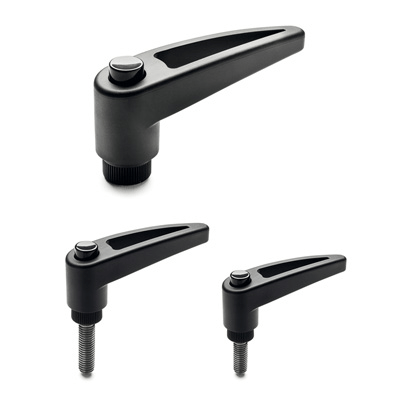
Glass-fibre reinforced technopolymer clamping element with retaining pin, black colour, with knurling on the protruding part to make initial tightening easier. AISI 302 stainless steel return spring.
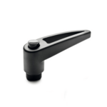
- MRT-B: brass boss, threaded blind hole.
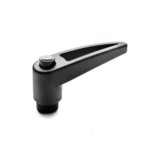
- MRT-SST: AISI 303 stainless steel boss, threaded blind hole.
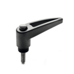
- MRT-p: zinc-plated steel threaded stud, chamfered flat end UNI 947 : ISO 4753 (see Technical data).
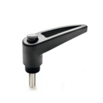
- MRT-SST-p: AISI 303 stainless steel threaded stud, chamfered flat end UNI 947 : ISO 4753 ( see Technical data).
Flat adjustable handle, open configuration to avoid any deposit of unhygienic residues or scraps and dirt.
Particularly suitable when the lever turning angle is limited owing to lack of space.
Compared to other types of adjustable handles with metal retaining screw this solution offers:
- absolute electric insulation for the operator
- no visible steel parts subject to rust
- more comfortable lever release.
Stress resistance
See ERX..
For clamping, lift the lever to disengage the clamping device teeth and bring it back to start position. By releasing the lever, the return spring automatically engages the teeth.
