
Velg deltype
Velg ønsket deltype for å se forhåndsvist tegning av tekniske dimensjoner
Bracket Material
Material
Bushing Material
Carrying Capacity
Diameter
Plunger Diameter
Type Of Assembly
Type Of Tube
Diameter Bases
Connecting Thread
External Diameter
Handle
Hole
Lever Length
Wheel Base
Threaded Screw
Hole Distance
Threaded Connection
Type Of Bellow
Type Of Vacuum Cups Holder
Vacuum Cup Holders Dimension
Vacuum Cups Dimension
Connector
Main specifications
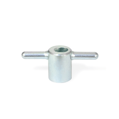
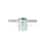
Standard execution
Zinc-plated steel hub, pass- through oblique hole, partially threaded.
The two lever arms are welded to the hub.
General information
Features and applications
The axial thread, intersecting with the oblique hole, creates the conditions allowing for quick tightening with just a few turns creating an effective tightening over many threads.
Other executions
Special executions on request
Stainless steel.
Instructions of use
Instructions for use
The nut thread must fit onto the pin in the axial position. All threads are engaged with a slight tightening.