
Velg deltype
Velg ønsket deltype for å se forhåndsvist tegning av tekniske dimensjoner
Bracket Material
Material
Bushing Material
Carrying Capacity
Diameter
Plunger Diameter
Type Of Assembly
Type Of Tube
Diameter Bases
Connecting Thread
External Diameter
Handle
Hole
Lever Length
Wheel Base
Threaded Screw
Hole Distance
Threaded Connection
Type Of Bellow
Type Of Vacuum Cups Holder
Vacuum Cup Holders Dimension
Vacuum Cups Dimension
Connector
Main specifications
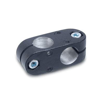
Material
Aluminium, epoxy resin coating, RAL 9005 black colour, matte finish.
AISI 304 stainless steel screws and nuts.
Standard executions
- GN 131.2-B-B: without sliding bushing.
- GN 131.2-G-G: with two polyamide based (PA) or polytetrafluoroethylene based (PTFE) technopolymer sliding bushings.
General information
Features and applications
GN 131.2 connecting clamps can normally be matched with the linear actuators.
By clamping the guide holes d1/d2 it is possible to adjust the actuator positioning and to lock the slider after having set up the final position.
The clamping screws d3 may be replaced by clamping kits GN 911.