GN 145.1

Linear actuators and clamp connectors

Teknisk datablad
553301-zcl_1_5_vd

Viser alle 2 resultater

    Description GN 145.1-B18-2-SW
    d1
    —
    • —
    d2
    —
    • —
    d3
    —
    • —
    d4
    —
    • —
    k
    —
    • —
    l
    —
    • —
    m
    —
    • —
    Thermometer
    —
    • —
    x
    —
    • —
    y1
    —
    • —
    y2
    —
    • —
    d3 Clamping kit
    —
    • —
    Weight
    —
    • —
    CAD
  • Description GN 145.1-B18-2-SW
    d1 -, 18
    d2 5.5
    d3 M6
    d4 M3
    k 25
    l 40
    m 18
    Thermometer 7
    x 35
    y1 50
    y2 38
    d3 Clamping kit GN 911-M6-22
    Weight 60
  • Description GN 145.1-G18-2-SW
    d1 -, 18
    d2 5.5
    d3 M6
    d4 M3
    k 25
    l 40
    m 18
    Thermometer 7
    x 35
    y1 50
    y2 38
    d3 Clamping kit GN 911-M6-22
    Weight 57
Main specifications
Material

Aluminium, epoxy resin coating, RAL 9005 black colour, matte finish.

AISI 304 stainless steel screw and nut.

Standard executions

  • GN 145.1-B: without sliding bushing.
  • GN 145.1-G: with polyamide based (PA) or polytetrafluoroethylene based (PTFE) technopolymer sliding bushing.
General information
Features and applications

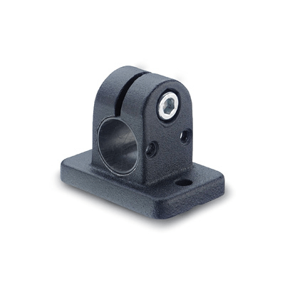
GN 145.1 connecting clamps can normally be matched with the linear actuators.

By clamping the guide hole d1 it is possible to adjust the actuator positioning and to lock the slider after having set up the final position.

The clamping screw d3 may be replaced by clamping kit GN 911.

Handlekurv
Skroll til toppen