

Velg deltype
Velg ønsket deltype for å se forhåndsvist tegning av tekniske dimensjoner
Bracket Material
Material
Bushing Material
Carrying Capacity
Diameter
Plunger Diameter
Type Of Assembly
Type Of Tube
Diameter Bases
Connecting Thread
External Diameter
Handle
Hole
Lever Length
Wheel Base
Threaded Screw
Hole Distance
Threaded Connection
Type Of Bellow
Type Of Vacuum Cups Holder
Vacuum Cup Holders Dimension
Vacuum Cups Dimension
Connector
Main specifications
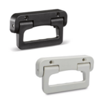
Material
Glass-fibre reinforced polyamide based (PA) technopolymer, RAL 9005 black colour or grey RAL 7040 (C33) colour, matte finish.
Standard execution
Pass-through holes for countersunk-head screws with cross mark ISO-7046-1-M6 (not included in the supply).
Rotation pin and return springs
AISI 303 stainless steel pin, AISI 302 stainless steel springs.
General information
Technical data
The lifting resistance (F1) and tensile strength (F2) values reported in the table are the result of permanent deformation by means of the appropriate dynamometric equipment under the test conditions shown in the figure with ambient temperature.
Instructions of use
Assembly instructions
Drill holes with centre distance 80 +0.1/-0.1 in the sheet.