GN 113.1

Lock pins

Teknisk datablad
CE.31611-277_vr_vr_i

Viser alle 8 resultater

    Description GN 113.1-6-0
    Position
    —
    • —
    d1 -0.04/-0.08
    —
    • —
    d2
    —
    • —
    d3
    —
    • —
    d4
    —
    • —
    l1 min.
    —
    • —
    l1 max.
    —
    • —
    l2
    —
    • —
    l3
    —
    • —
    Monting hole H7
    —
    • —
    Axial holding force ibf
    —
    • —
    Weight
    —
    • —
    CAD
  • Description GN 113.1-6-0
    Position 0
    d1 -0.04/-0.08 6
    d2 7
    d3 38
    d4 17.5
    l1 min. 0
    l1 max. 5
    l2 5
    l3 30
    Monting hole H7 6
    Axial holding force ibf 16
    Weight 16
  • Description GN 113.1-6-5
    Position 0
    d1 -0.04/-0.08 6
    d2 7
    d3 38
    d4 17.5
    l1 min. 5
    l1 max. 10
    l2 5
    l3 30
    Monting hole H7 6
    Axial holding force ibf 18
    Weight 23
  • Description GN 113.1-8-0
    Position 0
    d1 -0.04/-0.08 8
    d2 9.5
    d3 38
    d4 17.5
    l1 min. 0
    l1 max. 5
    l2 6.5
    l3 30
    Monting hole H7 8
    Axial holding force ibf 16
    Weight 19
  • Description GN 113.1-8-5
    Position 0
    d1 -0.04/-0.08 8
    d2 9.5
    d3 38
    d4 17.5
    l1 min. 5
    l1 max. 10
    l2 6.5
    l3 30
    Monting hole H7 8
    Axial holding force ibf 18
    Weight 20
  • Description GN 113.1-10-0
    Position 0
    d1 -0.04/-0.08 10
    d2 12
    d3 47
    d4 23
    l1 min. 0
    l1 max. 5
    l2 8.7
    l3 36
    Monting hole H7 10
    Axial holding force ibf 21
    Weight 38
  • Description GN 113.1-10-5
    Position 0
    d1 -0.04/-0.08 10
    d2 12
    d3 47
    d4 23
    l1 min. 5
    l1 max. 10
    l2 8.7
    l3 36
    Monting hole H7 10
    Axial holding force ibf 23
    Weight 39
  • Description GN 113.1-12-0
    Position 0
    d1 -0.04/-0.08 12
    d2 14
    d3 47
    d4 23
    l1 min. 0
    l1 max. 5
    l2 9.4
    l3 36
    Monting hole H7 12
    Axial holding force ibf 21
    Weight 42
  • Description GN 113.1-12-5
    Position 0
    d1 -0.04/-0.08 12
    d2 14
    d3 47
    d4 23
    l1 min. 5
    l1 max. 10
    l2 9.4
    l3 36
    Monting hole H7 12
    Axial holding force ibf 23
    Weight 44
Main specifications
Pin

AISI 303 stainless steel.

Balls

AISI 420C stainless steel.

Spring

AISI 631 stainless steel.
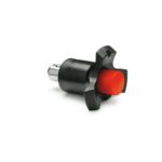
Three-lobe handle

Glass-fibre reinforced polyamide based (PA) technopolymer, black colour, provided with hole for security ring.

Button

Polyamide based (PA) technopolymer, red colour.

Working temperature

From -30°C to +80°C.

General information
Features and applications

GN 113.1 ball lock pins are generally used for quick fixation of components or parts to be machined, in particular for elements which need to be removed and reset continuously.

A typical application is the alignment and locking of the sheet during a welding process.

Accessories
Accessories on request

To optimise the use of these lock pins, have been designed:

Instructions of use
Instructions of use

By pressing the push button the two balls are freed by exerting a radial retaining action which allows the pin to be engaged or disengaged.

Handlekurv
Skroll til toppen