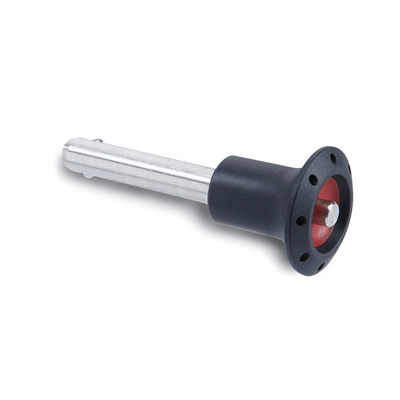
GN 113.5

Lock pins

Teknisk datablad
CE.31701-277_vr

Viser alle 29 resultater

    Description GN 113.5-5-10
    Position
    —
    • —
    d1 -0.04/-0.08
    —
    • —
    d2
    —
    • —
    d3
    —
    • —
    d4
    —
    • —
    l1 +0.6
    —
    • —
    l2 ±0.2
    —
    • —
    l3 -0.2
    —
    • —
    Monting hole H7
    —
    • —
    Double sided shearing force
    —
    • —
    Weight
    —
    • —
    CAD
  • Description GN 113.5-5-10
    Position ausgerastet
    d1 -0.04/-0.08 5
    d2 5.5
    d3 30
    d4 16
    l1 +0.6 10
    l2 ±0.2 6
    l3 -0.2 26
    Monting hole H7 5
    Double sided shearing force 14
    Weight 17
  • Description GN 113.5-5-15
    Position ausgerastet
    d1 -0.04/-0.08 5
    d2 5.5
    d3 30
    d4 16
    l1 +0.6 15
    l2 ±0.2 6
    l3 -0.2 26
    Monting hole H7 5
    Double sided shearing force 14
    Weight 20
  • Description GN 113.5-5-20
    Position ausgerastet
    d1 -0.04/-0.08 5
    d2 5.5
    d3 30
    d4 16
    l1 +0.6 20
    l2 ±0.2 6
    l3 -0.2 26
    Monting hole H7 5
    Double sided shearing force 14
    Weight 20
  • Description GN 113.5-5-25
    Position ausgerastet
    d1 -0.04/-0.08 5
    d2 5.5
    d3 30
    d4 16
    l1 +0.6 25
    l2 ±0.2 6
    l3 -0.2 26
    Monting hole H7 5
    Double sided shearing force 14
    Weight 20
  • Description GN 113.5-5-30
    Position ausgerastet
    d1 -0.04/-0.08 5
    d2 5.5
    d3 30
    d4 16
    l1 +0.6 30
    l2 ±0.2 6
    l3 -0.2 26
    Monting hole H7 5
    Double sided shearing force 14
    Weight 20
  • Description GN 113.5-6-10
    Position ausgerastet
    d1 -0.04/-0.08 6
    d2 7
    d3 30
    d4 16
    l1 +0.6 10
    l2 ±0.2 7.1
    l3 -0.2 26
    Monting hole H7 6
    Double sided shearing force 21
    Weight 20
  • Description GN 113.5-6-15
    Position ausgerastet
    d1 -0.04/-0.08 6
    d2 7
    d3 30
    d4 16
    l1 +0.6 15
    l2 ±0.2 7.1
    l3 -0.2 26
    Monting hole H7 6
    Double sided shearing force 21
    Weight 19
  • Description GN 113.5-6-20
    Position ausgerastet
    d1 -0.04/-0.08 6
    d2 7
    d3 30
    d4 16
    l1 +0.6 20
    l2 ±0.2 7.1
    l3 -0.2 26
    Monting hole H7 6
    Double sided shearing force 21
    Weight 20
  • Description GN 113.5-6-25
    Position ausgerastet
    d1 -0.04/-0.08 6
    d2 7
    d3 30
    d4 16
    l1 +0.6 25
    l2 ±0.2 7.1
    l3 -0.2 26
    Monting hole H7 6
    Double sided shearing force 21
    Weight 20
  • Description GN 113.5-6-30
    Position ausgerastet
    d1 -0.04/-0.08 6
    d2 7
    d3 30
    d4 16
    l1 +0.6 30
    l2 ±0.2 7.1
    l3 -0.2 26
    Monting hole H7 6
    Double sided shearing force 21
    Weight 23
  • Description GN 113.5-6-40
    Position ausgerastet
    d1 -0.04/-0.08 6
    d2 7
    d3 30
    d4 16
    l1 +0.6 40
    l2 ±0.2 7.1
    l3 -0.2 26
    Monting hole H7 6
    Double sided shearing force 21
    Weight 25
  • Description GN 113.5-8-20
    Position ausgerastet
    d1 -0.04/-0.08 8
    d2 9.5
    d3 35
    d4 19
    l1 +0.6 20
    l2 ±0.2 8.2
    l3 -0.2 32.5
    Monting hole H7 8
    Double sided shearing force 38
    Weight 42
  • Description GN 113.5-8-25
    Position ausgerastet
    d1 -0.04/-0.08 8
    d2 9.5
    d3 35
    d4 19
    l1 +0.6 25
    l2 ±0.2 8.2
    l3 -0.2 32.5
    Monting hole H7 8
    Double sided shearing force 38
    Weight 44
  • Description GN 113.5-8-30
    Position ausgerastet
    d1 -0.04/-0.08 8
    d2 9.5
    d3 35
    d4 19
    l1 +0.6 30
    l2 ±0.2 8.2
    l3 -0.2 32.5
    Monting hole H7 8
    Double sided shearing force 38
    Weight 50
  • Description GN 113.5-8-50
    Position ausgerastet
    d1 -0.04/-0.08 8
    d2 9.5
    d3 35
    d4 19
    l1 +0.6 50
    l2 ±0.2 8.2
    l3 -0.2 32.5
    Monting hole H7 8
    Double sided shearing force 38
    Weight 54
  • Description GN 113.5-10-20
    Position ausgerastet
    d1 -0.04/-0.08 10
    d2 12
    d3 35
    d4 19
    l1 +0.6 20
    l2 ±0.2 9.6
    l3 -0.2 32.5
    Monting hole H7 10
    Double sided shearing force 60
    Weight 50
  • Description GN 113.5-10-25
    Position ausgerastet
    d1 -0.04/-0.08 10
    d2 12
    d3 35
    d4 19
    l1 +0.6 25
    l2 ±0.2 9.6
    l3 -0.2 32.5
    Monting hole H7 10
    Double sided shearing force 60
    Weight 52
  • Description GN 113.5-10-30
    Position ausgerastet
    d1 -0.04/-0.08 10
    d2 12
    d3 35
    d4 19
    l1 +0.6 30
    l2 ±0.2 9.6
    l3 -0.2 32.5
    Monting hole H7 10
    Double sided shearing force 60
    Weight 55
  • Description GN 113.5-10-40
    Position ausgerastet
    d1 -0.04/-0.08 10
    d2 12
    d3 35
    d4 19
    l1 +0.6 40
    l2 ±0.2 9.6
    l3 -0.2 32.5
    Monting hole H7 10
    Double sided shearing force 60
    Weight 61
  • Description GN 113.5-10-50
    Position ausgerastet
    d1 -0.04/-0.08 10
    d2 12
    d3 35
    d4 19
    l1 +0.6 50
    l2 ±0.2 9.6
    l3 -0.2 32.5
    Monting hole H7 10
    Double sided shearing force 60
    Weight 60
  • Description GN 113.5-12-25
    Position ausgerastet
    d1 -0.04/-0.08 12
    d2 14.5
    d3 42
    d4 25
    l1 +0.6 25
    l2 ±0.2 10.6
    l3 -0.2 39
    Monting hole H7 12
    Double sided shearing force 87
    Weight 100
  • Description GN 113.5-12-30
    Position ausgerastet
    d1 -0.04/-0.08 12
    d2 14.5
    d3 42
    d4 25
    l1 +0.6 30
    l2 ±0.2 10.6
    l3 -0.2 39
    Monting hole H7 12
    Double sided shearing force 87
    Weight 100
  • Description GN 113.5-12-40
    Position ausgerastet
    d1 -0.04/-0.08 12
    d2 14.5
    d3 42
    d4 25
    l1 +0.6 40
    l2 ±0.2 10.6
    l3 -0.2 39
    Monting hole H7 12
    Double sided shearing force 87
    Weight 100
  • Description GN 113.5-12-50
    Position ausgerastet
    d1 -0.04/-0.08 12
    d2 14.5
    d3 42
    d4 25
    l1 +0.6 50
    l2 ±0.2 10.6
    l3 -0.2 39
    Monting hole H7 12
    Double sided shearing force 87
    Weight 120
  • Description GN 113.5-12-60
    Position ausgerastet
    d1 -0.04/-0.08 12
    d2 14.5
    d3 42
    d4 25
    l1 +0.6 60
    l2 ±0.2 10.6
    l3 -0.2 39
    Monting hole H7 12
    Double sided shearing force 87
    Weight 130
  • Description GN 113.5-16-30
    Position ausgerastet
    d1 -0.04/-0.08 16
    d2 19
    d3 42
    d4 25
    l1 +0.6 30
    l2 ±0.2 14
    l3 -0.2 39
    Monting hole H7 16
    Double sided shearing force 155
    Weight 140
  • Description GN 113.5-16-40
    Position ausgerastet
    d1 -0.04/-0.08 16
    d2 19
    d3 42
    d4 25
    l1 +0.6 40
    l2 ±0.2 14
    l3 -0.2 39
    Monting hole H7 16
    Double sided shearing force 155
    Weight 151
  • Description GN 113.5-16-50
    Position ausgerastet
    d1 -0.04/-0.08 16
    d2 19
    d3 42
    d4 25
    l1 +0.6 50
    l2 ±0.2 14
    l3 -0.2 39
    Monting hole H7 16
    Double sided shearing force 155
    Weight 170
  • Description GN 113.5-16-60
    Position ausgerastet
    d1 -0.04/-0.08 16
    d2 19
    d3 42
    d4 25
    l1 +0.6 60
    l2 ±0.2 14
    l3 -0.2 39
    Monting hole H7 16
    Double sided shearing force 155
    Weight 160
Main specifications
Pin and push button

AISI 303 stainless steel.

Balls

AISI 420C stainless steel.

Spring

Stainless steel.

Round handle

Glass-fibre reinforced polyamide based (PA) technopolymer, black and red colour, provided with holes for security ring

Working temperature

From -30°C to +80°C.

General information
Features and applications

GN 113.5 ball lock pins are generally used for quick fixation of components or parts to be machined, in particular for elements which need to be removed and reset continuously.

Accessories
Accessories on request

To optimise the use of these ball lock pins, have been designed:

Other executions
Special executions on request

Other dimensions.

Instructions of use
Instructions of use

By pressing the push button the two balls are freed by exerting a radial retaining action which allows the pin to be engaged or disengaged.

Handlekurv
Skroll til toppen