
Velg deltype
Velg ønsket deltype for å se forhåndsvist tegning av tekniske dimensjoner
Bracket Material
Material
Bushing Material
Carrying Capacity
Diameter
Plunger Diameter
Type Of Assembly
Type Of Tube
Diameter Bases
Connecting Thread
External Diameter
Handle
Hole
Lever Length
Wheel Base
Threaded Screw
Hole Distance
Threaded Connection
Type Of Bellow
Type Of Vacuum Cups Holder
Vacuum Cup Holders Dimension
Vacuum Cups Dimension
Connector
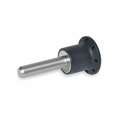
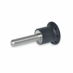
Main specifications
Pin
AISI 303 stainless steel.
Knob
Glass-fibre reinforced polyamide based (PA) technopolymer, grey-black colour, provided with holes for security ring.
Standard execution
(NdFeB) Neodymium-iron-boron retaining magnet, for temperatures up to 80°C.
General information
Features and applications
GN 124.1 self-locking pins are used for fast fixing between magnetic parts.
The presence of a neodymium magnet in the knob guarantees the maintenance of the pin in the axial retention position.
High-quality surfaces and precise perpendicularity of the positioning holes guarantee maximum efficiency of the magnetic flux.
Accessories