
GN_249_1
Spring plungers
Velg deltype
Velg ønsket deltype for å se forhåndsvist tegning av tekniske dimensjoner

Bracket Material
Material
Bushing Material
Carrying Capacity
Diameter
Plunger Diameter
Type Of Assembly
Type Of Tube
Diameter Bases
Connecting Thread
External Diameter
Handle
Hole
Lever Length
Wheel Base
Threaded Screw
Hole Distance
Threaded Connection
Type Of Bellow
Type Of Vacuum Cups Holder
Vacuum Cup Holders Dimension
Vacuum Cups Dimension
Connector
Main specifications
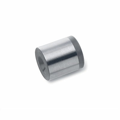
Material
Ground and hardened steel.
General information
Features and applications
GN 249.1 ball bushings are used together with ball or bolt spring plungers whenever a contact surface with high resistance to wear is required.
For an optimum plunger detention, the max distance “aâ€, obtained from the difference between the spring travel "w" of the chosen plunger and the ball depth “s†inside the ball bushing cavity, must not be exceeded.
In particular, they are recommended for use with plungers with high spring loads and plungers with reinforced spring.