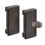
ESC

Latches with key

260361-C3-ebp-mdx50-sketch

Velg deltype

Velg ønsket deltype for å se forhåndsvist tegning av tekniske dimensjoner

Bracket Material
Material
Bushing Material
Carrying Capacity
Diameter
Plunger Diameter
Type Of Assembly
Type Of Tube
Diameter Bases
Connecting Thread
External Diameter
Handle
Hole
Lever Length
Wheel Base
Threaded Screw
Hole Distance
Threaded Connection
Type Of Bellow
Type Of Vacuum Cups Holder
Vacuum Cup Holders Dimension
Vacuum Cups Dimension
Connector

Viser alle 10 resultater

    Vennligst velg en deltype for å få relevante valg.

    Lukk
    Description ESC.90-BM-SS
    B
    —
    • —
    L
    —
    • —
    H
    —
    • —
    f
    —
    • —
    f1
    —
    • —
    f2
    —
    • —
    b1
    —
    • —
    b2
    —
    • —
    b3
    —
    • —
    h2
    —
    • —
    d
    —
    • —
    h1
    —
    • —
    C
    —
    • —
    Weight
    —
    • —
    CAD
  • Description ESC.90-BM-SS
    B 90
    L 72.5
    H 31
    f 72
    f1 40.5
    f2 13.5
    b1 25
    b2 47
    b3 25
    h2 7
    d 6
    h1 5
    C 5
    Weight 83
  • Description ESC.90-FM-SS
    B 90
    L 72.5
    H 31
    f 72
    f1 40.5
    f2 13.5
    b1 25
    b2 47
    b3 25
    h2 7
    d 6
    h1 5
    C 5
    Weight 83
  • Description ESC.90-BM-K-90-F
    B 90
    L 72.5
    H 31
    f 72
    f1 40.5
    f2 13.5
    b1 25
    b2 47
    b3 25
    h2 7
    d 6
    h1 5
    C 5
    Weight 115
  • Description ESC.90-FM-K-90-F
    B 90
    L 72.5
    H 31
    f 72
    f1 40.5
    f2 13.5
    b1 25
    b2 47
    b3 25
    h2 7
    d 6
    h1 5
    C 5
    Weight 115
  • Description ESC.90-BM-K-180-F
    B 90
    L 72.5
    H 31
    f 72
    f1 40.5
    f2 13.5
    b1 25
    b2 47
    b3 25
    h2 7
    d 6
    h1 5
    C 5
    Weight 115
  • Description ESC.90-FM-K-180-F
    B 90
    L 72.5
    H 31
    f 72
    f1 40.5
    f2 13.5
    b1 25
    b2 47
    b3 25
    h2 7
    d 6
    h1 5
    C 5
    Weight 115
  • Description ESC.90-BM-K-90-U
    B 90
    L 72.5
    H 31
    f 72
    f1 40.5
    f2 13.5
    b1 25
    b2 47
    b3 25
    h2 7
    d 6
    h1 5
    C 5
    Weight 115
  • Description ESC.90-FM-K-90-U
    B 90
    L 72.5
    H 31
    f 72
    f1 40.5
    f2 13.5
    b1 25
    b2 47
    b3 25
    h2 7
    d 6
    h1 5
    C 5
    Weight 115
  • Description ESC.90-BM-K-180-U
    B 90
    L 72.5
    H 31
    f 72
    f1 40.5
    f2 13.5
    b1 25
    b2 47
    b3 25
    h2 7
    d 6
    h1 5
    C 5
    Weight 115
  • Description ESC.90-FM-K-180-U
    B 90
    L 72.5
    H 31
    f 72
    f1 40.5
    f2 13.5
    b1 25
    b2 47
    b3 25
    h2 7
    d 6
    h1 5
    C 5
    Weight 115
Main specifications
Handle

Glass-fibre reinforced polyamide based (PA) technopolymer, black colour, matte finish. Acetal resin based (POM) technopolymer retention wings.

Stator and rotor

Nickel-plated zinc alloy.

Closing lever

Zinc-plated steel, 2 mm thickness.

Two keys

Nickel-plated brass.

Standard executions

General information
Features and applications
  • ESC door lock handle (ELESA patent) keeps the door locked in the closed position. Because of its location outside the door, its installation is very simple.
  • The handle dimensions are such as to allow the assembly on profiles with a minimum size of 25 mm and a maximum of 40 mm.
  • The handle is able to compensate for any misalignment of the door bringing it back to the correct position while closing by means of the built-in guides.
  • The handle is tamperproof from the outside thanks to the rear fastening (ESC.90-BM) or front fastening (ESC.90-FM) with caps not removable when the handle is closed and preventing access to the screws.
  • Under specific tests the handle has always maintained unchanged performance for over 40000 cycles.
Instructions of use
Assembly instructions

To ensure a correct opening release strength (45 N as long as the handle is assembled in best conditions), we recommend to position the two elements of the handle as close as possible (Fig. 1) during assembly.

Rear mounting by means of M6 hexagonal-head screws DIN 933 or M6 hexagonal nuts DIN 439B: place the screw as shown in Fig. 2. For ease of assembly with the nut, we recommend initially to fasten the nut as shown in the drawing.

Front mounting by means of M6 cylindrical-head screws: place the doorframe and the door by applying the relevant caps that prevent access to the screws (Fig. 3) (tamperproof).

Suggested tightening torque: 5 Nm.

Only when the door is open, it is possible to remove the caps with a screwdriver on both the door (Fig. 4) and the doorframe (Fig. 5).

Handlekurv
Skroll til toppen