MFE.

Toggle clamps

Teknisk datablad
CE.87950-rb_52

Viser alle 3 resultater

    Description MFE.80-AS
    Straight-line action stroke
    —
    • —
    b
    —
    • —
    d1
    —
    • —
    d2
    —
    • —
    d3
    —
    • —
    h1
    —
    • —
    h2
    —
    • —
    l1
    —
    • —
    l2
    —
    • —
    l3
    —
    • —
    l4
    —
    • —
    l5
    —
    • —
    s
    —
    • —
    Thermometer
    —
    • —
    w
    —
    • —
    Weight
    —
    • —
    CAD
  • Description MFE.80-AS
    Straight-line action stroke 0
    b 24
    d1 10
    d2 M6
    d3 M16x1.5
    h1 120
    h2 19
    l1 71
    l2 38
    l3 15.5
    l4 10
    l5 8
    s 24
    Thermometer 12
    w 21
    Weight 135
  • Description MFE.165-AS
    Straight-line action stroke 0
    b 28
    d1 12
    d2 M8
    d3 M20x1.5
    h1 194
    h2 22
    l1 113
    l2 59
    l3 20
    l4 16
    l5 9
    s 30
    Thermometer 15
    w 38
    Weight 335
  • Description MFE.340-AS
    Straight-line action stroke 0
    b 38
    d1 16
    d2 M10
    d3 M24x2
    h1 256
    h2 30
    l1 173
    l2 90
    l3 22
    l4 28
    l5 10
    s 36
    Thermometer 18
    w 66
    Weight 835
Main specifications
Material

C10 zinc-plated steel.

Rivets

Zinc-plated steel.

Push lever

Zinc-plated steel.

Reference bushing

Zinc-plated steel.

Nut

Zinc-plated steel.

Bushing fixing screws

Zinc-plated steel.

Handle

Polyurethane, red colour.

Fixing plate

Zinc-plated steel (to be ordered separately).

Clamping bolt

To be ordered separately.

General information
Features and applications

All articulated joints are lubricated with special grease.

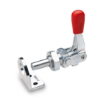
Thanks to the front outer thread, MFE. clamps can be mounted in a way that the control lever is conveniently positioned using fixing squares (to be ordered separately), or frontally directly on the equipment. Both push and pull clamping can be performed effectively.

Handlekurv
Skroll til toppen