MTB.

Toggle clamps

Teknisk datablad
CE.99253-fc_uc

Velg deltype

Velg ønsket deltype for å se forhåndsvist tegning av tekniske dimensjoner

Bracket Material
Material
Bushing Material
Carrying Capacity
Diameter
Plunger Diameter
Type Of Assembly
Type Of Tube
Diameter Bases
Connecting Thread
External Diameter
Handle
Hole
Lever Length
Wheel Base
Threaded Screw
Hole Distance
Threaded Connection
Type Of Bellow
Type Of Vacuum Cups Holder
Vacuum Cup Holders Dimension
Vacuum Cups Dimension
Connector

Viser alle 12 resultater

    Vennligst velg en deltype for å få relevante valg.

    Lukk
    Description MTB.160-T5
    Position
    —
    • —
    a
    —
    • —
    b1
    —
    • —
    b2
    —
    • —
    d
    —
    • —
    d1
    —
    • —
    h1
    —
    • —
    l
    —
    • —
    l1
    —
    • —
    m1
    —
    • —
    m2
    —
    • —
    s
    —
    • —
    r
    —
    • —
    FH
    —
    • —
    Weight
    —
    • —
    CAD
  • Description MTB.160-T5
    Position 0
    a 13
    b1 26
    b2 28
    d 4.5
    d1 -
    h1 26.8
    l -
    l1 103
    m1 16
    m2 19
    s 2
    r -
    FH 17500
    Weight 100
  • Description MTB.160-T5-TG
    Position 0
    a 13
    b1 26
    b2 23
    d 4.5
    d1 M6
    h1 19.8
    l 28
    l1 -
    m1 16
    m2 14.3
    s -
    r 55.5
    FH -
    Weight 134
  • Description MTB.160-T5-TU
    Position 0
    a 13
    b1 35
    b2 14
    d 4.5
    d1 M6
    h1 20.4
    l 28
    l1 -
    m1 25.4
    m2 -
    s -
    r 54.5
    FH -
    Weight 137
  • Description MTB.160-T5-TT
    Position 0
    a 13
    b1 26
    b2 14
    d 4.5
    d1 M6
    h1 20
    l 28
    l1 -
    m1 16
    m2 -
    s -
    r 55
    FH -
    Weight 127
  • Description MTB.320-T5
    Position 0
    a 19
    b1 40
    b2 44
    d 6.7
    d1 -
    h1 38.5
    l -
    l1 153
    m1 19
    m2 32
    s 3
    r -
    FH 40000
    Weight 295
  • Description MTB.320-T5-TG
    Position 0
    a 19
    b1 35
    b2 34
    d 6.7
    d1 M8
    h1 30
    l 34
    l1 -
    m1 19
    m2 22.3
    s -
    r 76.5
    FH -
    Weight 386
  • Description MTB.320-T5-TU
    Position 0
    a 19
    b1 38
    b2 18
    d 6.7
    d1 M8
    h1 28
    l 34
    l1 -
    m1 25.4
    m2 -
    s -
    r 76.25
    FH -
    Weight 379
  • Description MTB.320-T5-TT
    Position 0
    a 19
    b1 35
    b2 18
    d 6.7
    d1 M8
    h1 30
    l 34
    l1 -
    m1 19
    m2 -
    s -
    r 76.5
    FH -
    Weight 367
  • Description MTB.700-T5
    Position 0
    a 28
    b1 60
    b2 54
    d 8.5
    d1 -
    h1 53
    l -
    l1 222
    m1 41.5
    m2 38.1
    s 3.5
    r -
    FH 75000
    Weight 690
  • Description MTB.700-T5-TG
    Position 0
    a 28
    b1 50
    b2 41
    d 8.5
    d1 M10
    h1 40.5
    l 42
    l1 -
    m1 31
    m2 25.4
    s -
    r 95.5
    FH -
    Weight 894
  • Description MTB.700-T5-TU
    Position 0
    a 28
    b1 50
    b2 26
    d 8.5
    d1 M10
    h1 39
    l 42
    l1 -
    m1 31
    m2 -
    s -
    r 92.75
    FH -
    Weight 862
  • Description MTB.700-T5-TT
    Position 0
    a 28
    b1 50
    b2 26
    d 8.5
    d1 M10
    h1 40.5
    l 42
    l1 -
    m1 31
    m2 -
    s -
    r 93
    FH -
    Weight 844
Main specifications
Material

C10 phosphated steel.

Rivets

Zinc-plated steel.

Handle

Polyurethane, red colour.
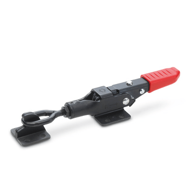
Standard executions

  • MTB.T5: without tie rod.
  • MTB.T5-TG: with eyelet tie rod.
  • MTB.T5-TT: with T tie rod
  • MTB.T5-TU: with hook tie rod.
General information
Features and applications

All articulated joints are lubricated with special grease.

MTB. latch clamps are particularly suitable for equipment and applications with strong vibration stresses where it is required to assure the holding of the clamp engagement against accidental opening.

By disengaging the safety stop, pushing the slider (fig. 1) and using the handle, the clamp opens (fig. 2). By disengaging the safety stop (fig. 3) and moving the control lever in the opposite direction (fig. 4), the result is the complete disengagement of the body of the clamp and the clamping plate.

To re-engage the clamp, it is necessary to proceed in the opposite way.

All these engaging and disengaging operations can be done by using one hand only, since in its movement the eyelet follows the lever.

The engaging position can be length-regulated in order to suit better the application by means of a threaded eyelet, locked in place by a locking nut.

Handlekurv
Skroll til toppen