
-

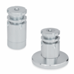
GN 360-B-NI
Grub-screws thrust pads ring washers
With locking nut, stainless steel
-
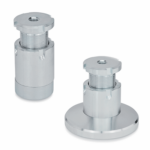
GN 360-A-ST
Grub-screws thrust pads ring washers
Without locking nut, zinc-plated steel
-
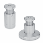
GN 360-B-ST
Grub-screws thrust pads ring washers
With locking nut, zinc-plated steel
-
GN 360-A-NI
Grub-screws thrust pads ring washers
Without locking nut, stainless steel
Main specifications
Standard executions
Zinc-plated steel:
- GN 360-A-ST: without locking nut.
- GN 360-B-ST: with locking nut.
AISI 304 stainless steel:
- GN 360-A-NI: without locking nut.
- GN 360-B-NI: with locking nut.
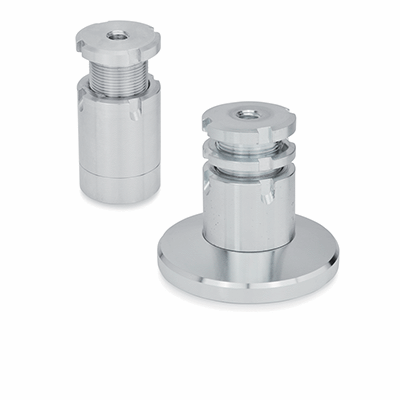
General information
Features and applications
GN 360 bushings are used for levelling and to compensate for any slopes when setting up machines.
D2 pass-through threading can also be used to fix the lower part of the bushing.
The fine pitch d3 threading allows for precision adjustment of the bushing and its eventual adjustment using a wrench.
An elastic ring limits the maximum adjustment stroke.
Dimensions GN 360-40/52/65: d1=d4
Dimensions GN 360-79/99/119: d4<d1
Other executions
Accessories on request
DIN 1810 spanner wrench.