
Velg deltype
Velg ønsket deltype for å se forhåndsvist tegning av tekniske dimensjoner
Bracket Material
Material
Bushing Material
Carrying Capacity
Diameter
Plunger Diameter
Type Of Assembly
Type Of Tube
Diameter Bases
Connecting Thread
External Diameter
Handle
Hole
Lever Length
Wheel Base
Threaded Screw
Hole Distance
Threaded Connection
Type Of Bellow
Type Of Vacuum Cups Holder
Vacuum Cup Holders Dimension
Vacuum Cups Dimension
Connector
Viser alle 35 resultater
Vennligst velg en deltype for å få relevante valg.
LukkMain specifications
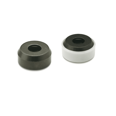
Types
- Type A: Thrust pad surface plane, without plastic cap
- Type K: Thrust pad surface plane, with plastic cap
- Type P: Thrust pad surface with detent, without plastic cap
Thrust pad
- Steel, blackened
- Stainless Steel AISI 304 NI
Elastic ring
Stainless Steel AISI 301
Plastic cap (Polyacetal POM)
- natural colour
- temperature resistant up to 100 °C
General information
Features and applications
GN 6311.1 thrust pads are used to transmit clamping forces by using grub screws DIN 6332.
The retaining ring creates a coupling between the grub screw and the thrust pad.
They can be adapted on irregular or non-parallel surfaces, holding the thrust pad with respect to the clamping surface, while tightening the screw.
The plastic cap (type K) prevents damage to delicate workpieces.