
Transparent polyamide based (PA-T) technopolymer. Highly resistant to shocks, solvents, oils with additives, aliphatic and aromatic hydrocarbons, petrol, naphtha, phosphoric esters.
Avoid contact with alcohol or detergents containing alcohol.
Screws, nuts and washers
Zinc-plated steel.
Packing rings
NBR synthetic rubber O-Ring.
Suggested roughness of the packing ring application surface Ra = 3 µm.
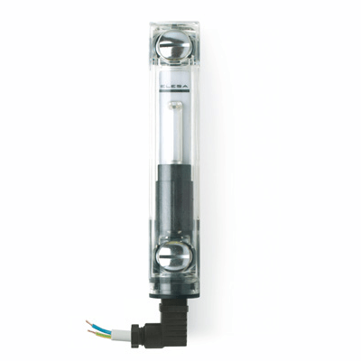
Float
Polyamide based (PA) expanded technopolymer, black colour, with a built-in magnetic element to activate the electric contact when the oil level drops to a minimum; alarm threshold located at about 50 mm from the centre of the lower nut (in presence of mineral oil type CB68, according to ISO 3498, at 23°C).
Floating is ensured by fluids with densities higher than 800 kg/m3.
Sensor bracket
Watertight in polypropylene based (PP) technopolymer, black colour, with a built-in relay (reed) with two conductors wired to the two-pin connector.
For a correct assembly see Warnings.
Swivelling two-pin connector
With built-in cable gland and contact holder. Front or side output (right or left) including protection against water sprays (protection class IP 65 according to EN 60529).
Contrast screen
White lacquered aluminium. The housing, in the appropriate external rear slot, guarantees the best protection from direct contact with fluid.
It can be taken out from the inclined side, before assembly to allow the insertion of level lines or words.
Standard execution
With electrical contacts normally closed.
Mounting
When fitting is not possible from the inside of the reservoir and the walls are not thick enough, the screws can be used together with Fast Mounting Kit.
Maximum continuous working temperature
90°C (with oil).
The column level indicator HCX-E, in addition to the visual control, generates an electric signal when the oil level drops to a minimum.
Ultrasound welding to guarantee a perfect seal.
Maximum fluid level visibility even from side positions.
Lens effect for a better visibility of the fluid level.
Technical data
In laboratory tests carried out with mineral oil type CB68 (according to ISO 3498) at 23°C for a limited period of time, the weld stood up to 13 bar.
For use with other fluids and under different pressure and temperature conditions, please contact ELESA Technical Department.
In any case we suggest to verify the suitability of the product under the actual working conditions.
HCX-E-NC: the electrical circuit is open when the minimum level is reached.
| Electrical features | MIN level sensor |
| Power supply | AC/DC |
| Electric contacts | NC normally closed |
| Maximum applicable voltage | NC: 150Vac, 150 Vdc |
| Maximum switching current | 1 A |
| Maximum current | NC: 2A |
| Maximum commutable power | NC: 20 Va |
| Cable gland | Pg 7 (for cables in sheath with Ø 6 or 7 mm) |
| Conductors cross-section | Max. 1.5 mm2 |
| Do not mount this indicator in proximity to magnetic fields. | |
- Level indicators for use with fluids containing alcohol.
- UV resistant transparent technopolymer indicators.
- Remove the connector from the indicator by unscrewing the set screw placed in the bottom, take the contact holder out and loosen the cable gland.
- Slip on the two-pole cable into the connector (standard connector) and connect the wires to the terminals nr. 1 and nr. 2 of the contact holder.
- Assemble by pressing the contact holder into the connector in the required position.
- Screw the connectors to the indicator and then tighten the cable glands.