

Velg deltype
Velg ønsket deltype for å se forhåndsvist tegning av tekniske dimensjoner
Transparent polyamide based (PA-T) technopolymer. High resistance to shocks, solvents, oils with additives, aliphatic and aromatic hydrocarbons, petrol, naphtha, phosphoric esters.
Avoid contact with alcohol or detergents containing alcohol.
Screws, nuts and washers
Zinc-plated steel.
Packing rings
NBR synthetic rubber O-Ring.
Suggested roughness of the packing ring application surface Ra = 3 µm.
Float
Ebonite, black colour.
Floating is ensured by fluids with densities higher than 800 kg/m3.
Contrast screen
White lacquered aluminium. The housing, in the appropriate external rear slot, guarantees the best protection from direct contact with fluid.
It can be taken out from the inclined side, before assembly to allow the insertion of level lines or words.
Mounting
When fitting is not possible from the inside of the reservoir and the walls are not thick enough, the screws can be used together with Fast Mounting Kit
Maximum continuous working temperature
90°C (with oil).
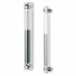
HCX-LT oil level indicator allows the fluid level reading by means of a float when, due to the particular design of the system, the fluid level cannot be seen directly from the lower part of the indicator.
The plastic foam float is moved upward by the fluid contained in the reservoir. This system allows an indirect reading of the level.
The red line on the lacquered contrast screen is visible only when the float is in its lowest position (minimun fluid level = m).
Ultrasound welding to guarantee a perfect seal.
Maximum fluid level visibility even from side positions.
Lens effect for a better visibility of the fluid level.
Technical data
In laboratory tests carried out with mineral oil type CB68 (according to ISO 3498) at 23°C for a limited period of time, the weld stood up to 12 bar.
For use with other fluids and under different pressure and temperature conditions, please contact ELESA Technical Department.
In any case we suggest to verify the suitability of the product under the actual working conditions.
- Level indicators with SUPER-technopolymer protection frame.
- UV resistant transparent technopolymer indicators.
To ensure proper assembly of the indicator, please follow these instructions:
- Set the minimum oil level of your reservoir.
- Drill two holes on the reservoir wall. The lower hole axis should be drilled at "m" distance (see table) under the minimum oil level.
"m" is the minimum oil level allowed. This is the level from which the float starts to be moved upward.
The value "m" is calculated with an oil density of 875 Kg/m³ at 15°C.
If the red line of the contrast screen appears, the oil level is under its minimum level allowed.