
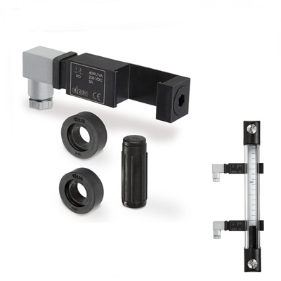
In polyamide based (PA) technopolymer, black colour, watertight, with a built-in relay (reed) with two conductors wired to the two-pin connector.
It can be moved along the axis of the indicator and secured in the preferred position with the appropriate screw (set screw) in technopolymer.
Electric sensor
- NO: the electric circuit closes on reaching the preset level.
- NC: the electric circuit opens on reaching the preset level.
Connector
With built-in cable gland and contact holder. Front or axial output (high or low) ensuring protection against water sprays (protection class IP 65 according to table EN 60529) that can be increased during installation with the necessary adjustments. NBR synthetic rubber packing rings.
Float
Polypropylene based (PP) technopolymer, max temperature limit 80° C or polyamide based (PA) technopolymer, max temperature limit 120°C, max chemical compatibility, black colour.
The float incorporates a magnetic element to activate the electric contact. When the float reaches the intervention level set by the user, by suitably positioning the sensor holder along the axis of the indicator, the electrical contact activates.
Max operating pressure 2 bar (operation with oil)
Spacer sleeves
In polyamide based (PA) technopolymer. Essential in cases where the reservoir is made out of ferromagnetic material in order to prevent the interaction between the magnet and the metal mass of the reservoir.
Kit
The kit includes one or two sensor holder brackets, a float, 4 O-rings (2 FKM for HCK-GL and 2 NBR for HCK), two spacers and two M12 UNI 5589 AISI 316 stainless steel nuts.
It is possible to apply more than one kit to get the electric control of different levels, consistently with the height of the transparent column.
Standard executions
For applications with temperatures up to 80°C: polypropylene based (PP) technopolymer float.
- SLCK-NO: with electric contact normally open.
- SLCK-NC: with electric contact normally closed.
- SLCK-NO-NC: with one electric contact normally open and one electric contact normally closed.
- SLCK-NC-NC: with two electric contacts normally closed.
- SLCK-NO-NO: with two electric contacts normally open.
For applications with temperatures up to 120°C: polyamide based (PA) technopolymer float.
- SLCK-HT-NO: with electric contact normally open.
- SLCK-HT-NC: with electric contact normally closed.
- SLCK-HT-NO-NC: with one electric contact normally open and one electric contact normally closed.
- SLCK-HT-NC-NC: with two electric contacts normally closed.
- SLCK-HT-NO-NO: with two electric contacts normally open.
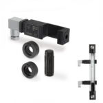
With the application of the SLCK kit, HCK. and HCK-GL column level indicators provide an electric signal when the fluid level reaches the level of preset intervention, besides the visual control of the level. The electric control of the level can be applied on all versions of HCK. from the version with 127 mm hole centre distance while always maintaining the visibility of fluid level even from side positions.
In the highest position, the sensor holder must be positioned at least 45 mm below the axis of the high screw (Fig.1), so that the switching takes place correctly.
In the lowest position, the fluid level which determines the switching of the electric circuit is about 55 mm above the axis of the low screw of fluid supply (data referring to mineral oil type CB68, according to ISO 3498, temperature 23°C) (Fig. 1).
The sensor holder is arranged to be installed to the left with respect to the axis of the indicator. However, if required it can also be mounted on the right. The connector can be rotated by 90° in four positions when wiring.
For a correct assembly see Warnings.
- Remove the assembly end of the indicator (Fig. 2).
- Insert the sensor holder bracket (Fig.3).
- Insert the float with the word "up" or the spherical end to the top and relocate the assembly end in place (Fig.4).
- Clamp the bracket with the set screw to the desired position (Fig. 5).
- Install the indicator on the reservoir using the spacers included in the supply (necessary in case of reservoir made out of ferromagnetic material in order to avoid interaction between the magnet and the metal mass (Fig.6).
- If the walls of the tank are thin and therefore it is not possible to have threaded holes, use the nuts supplied (max door thickness = 2 mm) (Fig.6.1).
- Assemble the two-pin connector (Fig. 7).
Two-pin connector assembly instructions
- Remove the connector from the sensor holder bracket by unscrewing the axial set screw, take off the contact holder and unscrew the cable gland as required.
- Slip on the cable into the connector and connect the wires to the terminals of the contact holder.
- Assemble by pressing the contact holder into the connector (the contact holder can be rotated by 90° in four positions to have a different orientation of the connector).
- Screw again the connector to the sensor holder by means of the axial set screw and then tighten the cable gland.
| Level sensor electric characteristics | |
|---|---|
| Power supply | AC/DC |
| Electric contacts | NO normally open NC normally closed |
| Maximum applicable voltage | 230 Vdc / Vac |
| Maximum current (CC CA) | 2 A |
| Maximum commutable power | 40 W / VA |
| Cable gland | Pg 7 (for cables in sheath with Ø 6 or 7 mm) |
| Conductors cross-section | Max. 1.5 mm2 |
| Do not mount this indicator in proximity to magnetic fields. | |