
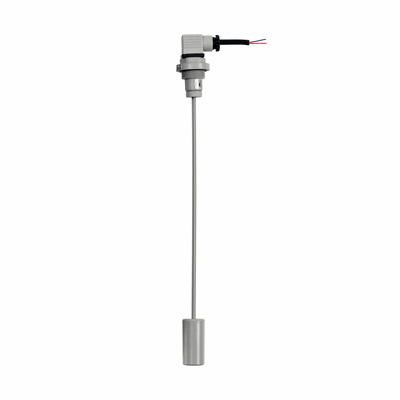
Body, dipstick and float: polyamide based (PA) technopolymer, grey colour.
Packing rings
- TPE flat gasket (HFLT-EF).
- NBR synthetic rubber O-Ring (HFLT-ER).
Connector
EN 175301-803 (A and C shape) / ISO 4400
Dipstick
Featuring two raised scales (for floatation in oil and water)
Standard executions
- HFLT-EF: assembly by means of a flange with 3 holes at 120° for 3 zinc-plated steel screws with hexagon socket, supplied, and a threaded coupler.
- HFLT-ER: assembly by means of a threaded coupler.
Maximum continuous working temperature: 80° C.
HFLT-E rapid levels detects a predefined minimum or maximum level, according to the application needs.
Highly versatile, these rapid levels allow to define both the most accurate set point required by simply disassembling the dipstick float and cutting the dipstick exactly where needed (see Fig.1).
After selecting the scale corresponding to the liquid used (water-oil), it is necessary to cut the rod at the point corresponding to the control level.
The kind of operation required, with normally open (NO) or normally closed (NC) contact in presence of liquid, by loosening the fastening nut on the opposite end of the dipstick and positioning the inner magnet according to specific requirements (refer to the adhesive label) (see Fig.2).
The magnet is generally supplied with normally open (NO) contact in presence of liquid.
Free from magnetic parts, the float is integral to the dipstick making this level indicator ideal for use in tanks containing dirty liquids, water, oil, coolant oil, also with iron metal parts or foams. Moreover, the operation is independent of the fluid electrical conductivity.
To ensure utmost safety, the electrical components are separated from the tank and perfectly sealed by means of ultrasound welding.

Functioning of the electrical sensor
HFLT-NO (standard condition of supply): the electrical contact opens when the liquid reaches the desired intervention level.
HFLT-NC (condition after specific configuration): the electrical contact closes when the liquid reaches the desired intervention level.
| Electrical features | |
|---|---|
| Power supply | AC/DC |
| Electric contacts | NO (standard supply) NC (after specific configuration) |
| Maximum commutable voltage | 230 Vdc, 230 Vac |
| Maximum current | 2 A |
| Commutable power | 40 W 40 VA |
| Cable gland | Pg 9 / Pg 11 UNIFIED |
| Conductors cross-section | Max. 1.5 mm2 |
| Protection | IP 65 |
- Polypropylene body (PP).
- With flange with 6 holes for fastening with cylindrical head screws (supplied), in addition to the threaded body.
- For use with maximum working temperature up to 120°C.
- Remove the connectors from the indicator by unscrewing the set screw placed in the bottom, take the contact holders out and loosen the cable glands.
- Slip on the two-pole cable into the connectors (standard connectors) and connect the wires to the terminals nr. 1 and nr. 2 of the relative contact holders.
- Assemble by pressing the contact holders into the relative connectors in the required position.
- Screw the connectors to the indicator and then tighten the cable glands.