Vi holder feriestengt i uke 30, vi ønsker alle besøkere en riktig god sommer!

VLSK

Lobe knobs

Teknisk datablad
GN.32033-gn_949_a
Bracket Material
Material
Bushing Material
Carrying Capacity
Diameter
Plunger Diameter
Type Of Assembly
Type Of Tube
Diameter Bases
Connecting Thread
External Diameter
Handle
Hole
Lever Length
Wheel Base
Threaded Screw
Hole Distance
Threaded Connection
Type Of Bellow
Type Of Vacuum Cups Holder
Vacuum Cup Holders Dimension
Vacuum Cups Dimension
Connector

Viser alle 16 resultater

    Vennligst velg en deltype for å få relevante valg.

    Lukk
    Code 76701
    Description VLSK.63 B-M6-F
    D
    —
    • —
    d6H
    —
    • —
    L
    —
    • —
    d1
    —
    • —
    l2
    —
    • —
    h
    —
    • —
    Weight
    —
    • —
    CAD
  • Code 76701
    Description VLSK.63 B-M6-F
    D 63
    d6H M6
    L 44
    d1 23
    l2 17
    h 18
    Weight 95
  • Code 76702
    Description VLSK.63 B-M8-F
    D 63
    d6H M8
    L 44
    d1 23
    l2 17
    h 18
    Weight 94
  • Code 76703
    Description VLSK.63 B-M10-F
    D 63
    d6H M10
    L 44
    d1 23
    l2 17
    h 20
    Weight 93
  • Code 76711
    Description VLSK.63 FP-M6-F
    D 63
    d6H M6
    L 44
    d1 23
    d3 14
    l2 17
    h 18
    Weight 95
  • Code 76712
    Description VLSK.63 FP-M8-F
    D 63
    d6H M8
    L 44
    d1 23
    d3 14
    l2 17
    h 18
    Weight 94
  • Code 76713
    Description VLSK.63 FP-M10-F
    D 63
    d6H M10
    L 44
    d1 23
    d3 14
    l2 17
    h 20
    Weight 93
  • Code 76731
    Description VLSK.63 p-M8x20-F
    D 63
    d6g M8
    L 44
    d1 23
    l 20
    l2 17
    Weight 106
  • Code 76741
    Description VLSK.63 p-M10x20-F
    D 63
    d6g M10
    L 44
    d1 23
    l 20
    l2 17
    Weight 107
  • Code 76801
    Description VLSK.63 B-M6-U
    D 63
    d6H M6
    L 44
    d1 23
    l2 17
    h 18
    Weight 95
  • Code 76802
    Description VLSK.63 B-M8-U
    D 63
    d6H M8
    L 44
    d1 23
    l2 17
    h 18
    Weight 94
  • Code 76803
    Description VLSK.63 B-M10-U
    D 63
    d6H M10
    L 44
    d1 23
    l2 17
    h 20
    Weight 93
  • Code 76811
    Description VLSK.63 FP-M6-U
    D 63
    d6H M6
    L 44
    d1 23
    d3 14
    l2 17
    h 18
    Weight 95
  • Code 76812
    Description VLSK.63 FP-M8-U
    D 63
    d6H M8
    L 44
    d1 23
    d3 14
    l2 17
    h 18
    Weight 94
  • Code 76813
    Description VLSK.63 FP-M10-U
    D 63
    d6H M10
    L 44
    d1 23
    d3 14
    l2 17
    h 20
    Weight 93
  • Code 76831
    Description VLSK.63 p-M8x20-U
    D 63
    d6g M8
    L 44
    d1 23
    l 20
    l2 17
    Weight 106
  • Code 76841
    Description VLSK.63 p-M10x20-U
    D 63
    d6g M10
    L 44
    d1 23
    l 20
    l2 17
    Weight 107
Main specifications
Lobe solid cap and coloured centre cap

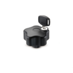
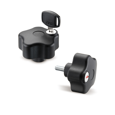
Glass-fibre reinforced polyamide based (PA) technopolymer, black colour, matte finish, with slot for codified key.

Flange

Technopolymer, ultrasonically welded.

Clamping element

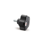
Glass-fibre reinforced polyamide based (PA) SUPER-technopolymer, black colour, matte finish.

Standard executions

  • VLSK-B: brass boss, threaded pass-through hole, with cap.
  • VLSK-FP: brass boss, threaded pass-through hole, without cap.
  • VLSK-p: zinc-plated steel threaded stud, chamfered flat end UNI 947 : ISO 4753 (see Technical data), with cap.

Indexes to add to the above mentioned executions:

  • F: lock with 210 different combinations; each lock has a couple of keys with different combination, removable in two positions at 180°.
  • U: lock with one combination; all locks have the same combination and can be opened with the same key removable in two positions at 180°.

Lock and keys

Die cast zinc alloy rotor and stator.

The lock has got a red protection tab for closing the lock when the key is not inserted.

Two keys made out of nickel-plated brass and technopolymer.

General information
Security device operation

VLSK. security lobe knob has been designed to prevent its unscrewing by unauthorised people. Therefore, it has got a vandal-proof function as well.

For clamping and unscrewing the knob, insert the special key into the lock and turn it by 180°. By so doing the clamping element and the knob form a single body. When the lock is brought back to the starting position and the key is removed, the knob turns freely preventing the unscrewing.

Features and applications

The particular design of the internal device and of the flange helps the drainage of any dirt (dust, earth or liquid).

Handlekurv
Skroll til toppen