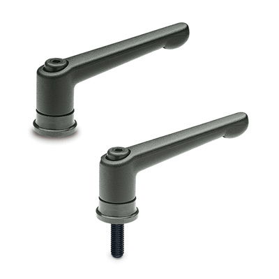
GN 300.4

Adjustable handles

Teknisk datablad
GN.68275-gn_923_a_b

Viser alle 15 resultater

    Description GN 300.4-63-M6-SW
    l1
    —
    • —
    d1
    —
    • —
    d3
    —
    • —
    d4
    —
    • —
    h1
    —
    • —
    h2
    —
    • —
    h3
    —
    • —
    h4
    —
    • —
    t min
    —
    • —
    Wight
    —
    • —
    CAD
  • Description GN 300.4-63-M6-SW
    l1 63
    d1 M6
    d3 24
    d4 17.5
    h1 34.5
    h2 11
    h3 48.5
    h4 4
    t min 12.5
    Wight 96
  • Description GN 300.4-78-M8-SW
    l1 78
    d1 M8
    d3 25
    d4 21
    h1 39.5
    h2 11.5
    h3 58.5
    h4 4
    t min 14
    Wight 140
  • Description GN 300.4-92-M10-SW
    l1 92
    d1 M10
    d3 30
    d4 24
    h1 46.5
    h2 13.5
    h3 68.5
    h4 4
    t min 18
    Wight 205
  • Description GN 300.4-108-M12-SW
    l1 108
    d1 M12
    d3 35
    d4 30
    h1 56.5
    h2 18
    h3 82
    h4 5
    t min 26.5
    Wight 325
  • Description GN 300.4-63-M6-20-SW
    l1 63
    d1 M6
    d3 24
    d4 17.5
    h1 34.5
    h2 11
    h3 48.5
    h4 4
    l2 20
    Weight 99
  • Description GN 300.4-63-M6-27-SW
    l1 63
    d1 M6
    d3 24
    d4 17.5
    h1 34.5
    h2 11
    h3 48.5
    h4 4
    l2 27
    Weight 103
  • Description GN 300.4-78-M8-21-SW
    l1 78
    d1 M8
    d3 25
    d4 21
    h1 39.5
    h2 11.5
    h3 58.5
    h4 4
    l2 21
    Weight 152
  • Description GN 300.4-78-M8-36-SW
    l1 78
    d1 M8
    d3 25
    d4 21
    h1 39.5
    h2 11.5
    h3 58.5
    h4 4
    l2 36
    Weight 156
  • Description GN 300.4-92-M10-29-SW
    l1 92
    d1 M10
    d3 30
    d4 24
    h1 46.5
    h2 13.5
    h3 68.5
    h4 4
    l2 29
    Weight 218
  • Description GN 300.4-92-M10-47-SW
    l1 92
    d1 M10
    d3 30
    d4 24
    h1 46.5
    h2 13.5
    h3 68.5
    h4 4
    l2 47
    Weight 223
  • Description GN 300.4-108-M12-34-SW
    l1 108
    d1 M12
    d3 35
    d4 30
    h1 56.5
    h2 18
    h3 82
    h4 5
    l2 34
    Weight 366
  • Description GN 300.4-108-M12-50-SW
    l1 108
    d1 M12
    d3 35
    d4 30
    h1 56.5
    h2 18
    h3 82
    h4 5
    l2 50
    Weight 382
  • Description GN 300.4-108-M12-57-SW
    l1 108
    d1 M12
    d3 35
    d4 30
    h1 56.5
    h2 18
    h3 82
    h4 5
    l2 57
    Weight 389
  • Description GN 300.4-108-M12-65-SW
    l1 108
    d1 M12
    d3 35
    d4 30
    h1 56.5
    h2 18
    h3 82
    h4 5
    l2 65
    Weight 397
  • Description GN 300.4-108-M12-85-SW
    l1 108
    d1 M12
    d3 35
    d4 30
    h1 56.5
    h2 18
    h3 82
    h4 5
    l2 85
    Weight 417
Main specifications
Lever body

Die-cast zinc alloy, epoxy resin coating, RAL 9005 black colour, matte finish.
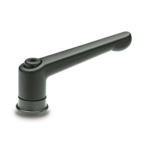
Distance bushing

Nitrided tempered steel with balls allowing a greater efficacy of the clamping force.

Standard executions

Black-oxide steel clamping element and retaining screw. Steel return spring.

Retaining screw with six-lobed socket to fit TORX®* (see communication attached).

  • Threaded hole.
  • Threaded screw, length as shown in the table.
General information
Features and applications

Adjustable handles GN 300.4 allow a higher tightening clamp force.

The clamping element is not in direct contact with the plane to be clamped. Clamping is made by the distance bushing with large base, which does not rotate on the plane. The bushing contains a set of balls which reduce to a minimum friction between the part which rotates with the lever during clamping and the distance bushing.

Other executions
Special executions on request

Lever in different colours.

Instructions of use
Instructions of use

For clamping, lift the lever to disengage the clamping device teeth and bring it back to start position. By releasing the lever, the return spring automatically engages the teeth.

If the lever cannot make a 360° rotation, the clamping element can be easily screwed by means of the six-lobed socket front head screw (after having disengaged the lever).

* Registered trademark by TEXTRON INC.

Handlekurv
Skroll til toppen