
Velg deltype
Velg ønsket deltype for å se forhåndsvist tegning av tekniske dimensjoner

Bracket Material
Material
Bushing Material
Carrying Capacity
Diameter
Plunger Diameter
Type Of Assembly
Type Of Tube
Diameter Bases
Connecting Thread
External Diameter
Handle
Hole
Lever Length
Wheel Base
Threaded Screw
Hole Distance
Threaded Connection
Type Of Bellow
Type Of Vacuum Cups Holder
Vacuum Cup Holders Dimension
Vacuum Cups Dimension
Connector
Main specifications
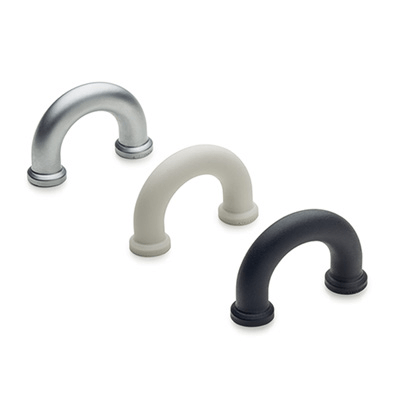
Material
Polyamide based (PA) technopolymer, in 4 standard colours: black, orange, grey, red, matte finish.
Standard execution
Blind holes for fitting by means of no. 2 self-tapping screws for plastic materials Ø3.5 (UNI ISO 7049), not included in the supply.
Maximum tightening torque of the self-tapping screws 1,2 [Nm].
General information
Technical data
Tensile stress and impact strength: the values F2 and L1 indicated in the table were obtained during breaking tests carried out with the appropriate dynamometric equipment under the test conditions shown in the figure with ambient temperature.