
Velg deltype
Velg ønsket deltype for å se forhåndsvist tegning av tekniske dimensjoner
Bracket Material
Material
Bushing Material
Carrying Capacity
Diameter
Plunger Diameter
Type Of Assembly
Type Of Tube
Diameter Bases
Connecting Thread
External Diameter
Handle
Hole
Lever Length
Wheel Base
Threaded Screw
Hole Distance
Threaded Connection
Type Of Bellow
Type Of Vacuum Cups Holder
Vacuum Cup Holders Dimension
Vacuum Cups Dimension
Connector
Main specifications
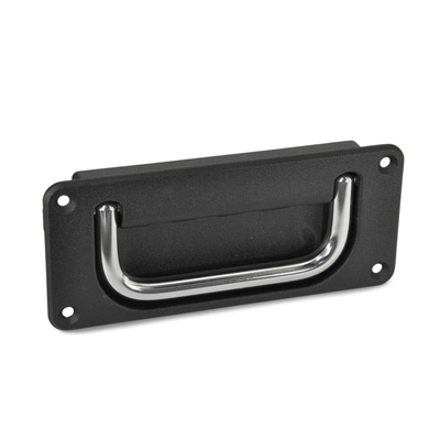
Tray
Die-cast zinc alloy, epoxy resin coating, matte finish.
Pass-through holes for M4 countersunk-head screws.
Standard executions
- GN 425.8-CR-A: chrome-plated steel handle. Click device to stop the handle in both positions.
- GN 425.8-CR-B: chrome-plated steel handle. Handle with return spring from work to rest position.
- GN 425.8-NI-A: AISI 304 stainless steel handle, sandblasted matte finish. Click device to stop the handle in both positions.
- GN 425.8-NI-B: AISI 304 stainless steel handle, sandblasted matte finish. Handle with return spring from work to rest position.
- SW version: in RAL 9005 black colour.
- versione SR: RAL 9006 grey colour.
General information
Features and applications
GN 425.8 handle is particularly suitable in order to save space. The tray protrudes from the assembly surface by only 3 mm.