MPR

Flush pull handles

Teknisk datablad
CE.20031-ga01_ga02_ga05

Viser alle 6 resultater

    Description MPR.141-CLEAN
    Position
    —
    • —
    B
    —
    • —
    f1
    —
    • —
    f2
    —
    • —
    L
    —
    • —
    H
    —
    • —
    h1
    —
    • —
    h2
    —
    • —
    b1
    —
    • —
    l1
    —
    • —
    l2
    —
    • —
    s
    —
    • —
    d
    —
    • —
    F1
    —
    • —
    F2
    —
    • —
    Weight
    —
    • —
    CAD
  • Description MPR.141-CLEAN
    Position 1
    B 141
    f1 118
    f2 79
    L 96
    H 19
    h1 16
    h2 63
    b1 90
    l1 16.5
    l2 29
    s 3
    d 4.2
    F1 1650
    F2 2400
    Weight 146
  • Description MPR.167-CLEAN
    Position 1
    B 167
    f1 141
    f2 98
    L 116
    H 21
    h1 18
    h2 78
    b1 105
    l1 17.3
    l2 43
    s 3
    d 5.2
    F1 -
    F2 -
    Weight 214
  • Code 43851
    Description MPR.141
    Position 1
    B 141
    f1 118
    f2 79
    L 96
    H 19
    h1 16
    h2 63
    b1 90
    l1 16.5
    l2 29
    s 3
    d 4.2
    F1 1650
    F2 2400
    Weight 146
  • Description MPR.141-C33
    Position 1
    B 141
    f1 118
    f2 79
    L 96
    H 19
    h1 16
    h2 63
    b1 90
    l1 16.5
    l2 29
    s 3
    d 4.2
    F1 1650
    F2 2400
    Weight 146
  • Code 43861
    Description MPR.167
    Position 1
    B 167
    f1 141
    f2 98
    L 116
    H 21
    h1 18
    h2 78
    b1 105
    l1 17.7
    l2 43
    s 3
    d 5.2
    F1 -
    F2 -
    Weight 214
  • Description MPR.167-C33
    Position 1
    B 167
    f1 141
    f2 98
    L 116
    H 21
    h1 18
    h2 78
    b1 105
    l1 17.3
    l2 43
    s 3
    d 5.2
    F1 -
    F2 -
    Weight 214
Main specifications
Material

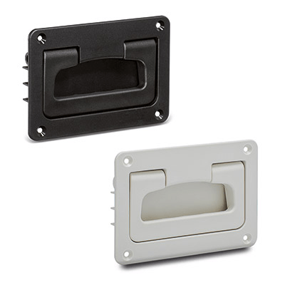
Glass-fibre reinforced polyamide based (PA) technopolymer, RAL 9005 black colour or grey RAL 7040 (C33) colour, matte finish.

Standard execution

Pass-through holes for M4 or M5 countersunk-head screws (not supplied).

Rotation pin and return springs

AISI 303 stainless steel pin, AISI 302 stainless steel springs.

General information
Technical data

The lifting resistance (F1) and tensile strength (F2) values reported in the table are the result of permanent deformation by means of the appropriate dynamometric equipment under the test conditions shown in the figure with ambient temperature.

Instructions of use
Assembly instructions

Drill the handle housing according to the template dimensions.

 xyf1f2
MPR.141135+0.265+0,2118+/-0,179+/-0,1
MPR.167158-0.286-0,2141+/-0,198+/-0,1
Handlekurv
Skroll til toppen