

Main specifications
Standard components
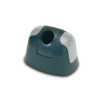
- MSR.60-B base: glass-fibre reinforced polyamide based (PA) technopolymer, black colour, matte finish.
- CC-MSR.60 screw covers: polyester based (PBT) technopolymer in six colours, glossy finish press-fit assembly. Supplied, removable by a screwdriver.
Available also as accessory sold separately (see table).
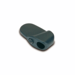
- MSR.60-C Two-way clamp: glass-fibre reinforced polyamide based (PA) technopolymer, black colour, matte finish.
- MSR.60-TA-TB-TC-TD-TE-TF device clamps: glass-fibre reinforced polyamide based (PA) technopolymer.
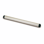
- MSR.60-T13 connecting tubes: aluminium profile available with standard lengths from 100 to 2000 mm.
On request and for sufficient quantities other lengths are available.
- TC13-MSR.60 connecting tube closing caps: glass-fibre reinforced polyamide based (PA) technopolymer, black colour, matte finish, push-fit assembly. Supplied.
Available also as accessory sold separately (see table).
General information
Features and applications
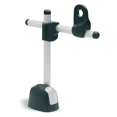
MSR. connecting clamps, designed according to ELESA patent, allow an easy and efficient connection between the components, preventing the risk of rotating freely.
The system allows the axial, perpendicular or angled positioning of the connecting tube to the base.
Advantages
- The slot-shaped connecting tube prevents free rotation.
- Tube and components clamped by the aid of only one screw.
- Easy adjustments by five degrees of freedom of the clamped devices (see drawing).
- Lack of cavities to avoid the deposit of dirt and undesired substances.
- Easy identification of the clamped device using different coloured caps on the base.
Instructions of use
Assembly instructions
- Assemble the base by means of 2 M6 cylindrical head screws with hexagon socket (not supplied).
- Fit one of the closing caps to the end of the connecting tube by tapping gently with a plastic mallet until firmly in place. Be careful not to assemble the cap to the end fitted to the base.
- Insert the connecting tube in the shaped hole of the base and clamp it by screwing the set screw. Suggested tightening torque 5 Nm.
- Insert the connecting tube in the shaped hole of the two-way clamp.
- Fit the closing caps to the connecting tube.
- Insert the connecting tube in the shaped hole of the two-way clamp.
- Fit on the connecting tube the proper device clamp, chosen within the six available. After the positioning of the components, clamp them by screwing the set screws. Suggested tightening torque 3 Nm. We recommend not to exceed this value.
- Once the adjustment has been set, fit the screw covers on the base.
Accessories
Accessories on request
- CC-MSR.60: screw-covers in polyester based technopolymer (PBT) in six colours, glossy finish, press-fit assembly (see table).
- TC13-MSR.60: glass-fibre reinforced polyamide based (PA) technopolymer connecting tube closing caps, black colour, matte finish, press-fit assembly (see table).