SPR.V

Supports and guides

Teknisk datablad
CE.74281-pa11_pa12

Viser alle 6 resultater

    Description SPR.V-12-B
    d Pin
    —
    • —
    H
    —
    • —
    L
    —
    • —
    B
    —
    • —
    f
    —
    • —
    f1
    —
    • —
    b1
    —
    • —
    h1
    —
    • —
    h2
    —
    • —
    h3
    —
    • —
    l1
    —
    • —
    l2
    —
    • —
    l3
    —
    • —
    Weight
    —
    • —
    CAD
  • Description SPR.V-12-B
    d Pin 12
    H 238
    L 85
    B 41
    f 69
    f1 90
    b1 11
    h1 11
    h2 100
    h3 70
    l1 8
    l2 43
    l3 64
    Weight 270
  • Description SPR.V-14-B
    d Pin 14
    H 238
    L 85
    B 41
    f 69
    f1 90
    b1 11
    h1 11
    h2 100
    h3 70
    l1 8
    l2 43
    l3 64
    Weight 265
  • Description SPR.V-16-B
    d Pin 16
    H 238
    L 85
    B 41
    f 69
    f1 90
    b1 11
    h1 11
    h2 100
    h3 70
    l1 8
    l2 43
    l3 64
    Weight 260
  • Description SPR.V-12-A
    d Pin 12
    H 203
    L 70
    B 37
    f 42
    f1 79
    b1 11
    h1 15
    h2 76
    h3 60
    l1 8
    l2 30
    l3 50
    Weight 255
  • Description SPR.V-14-A
    d Pin 14
    H 203
    L 70
    B 37
    f 42
    f1 79
    b1 11
    h1 15
    h2 76
    h3 60
    l1 8
    l2 30
    l3 50
    Weight 250
  • Description SPR.V-16-A
    d Pin 16
    H 203
    L 70
    B 37
    f 42
    f1 79
    b1 11
    h1 15
    h2 76
    h3 60
    l1 8
    l2 30
    l3 50
    Weight 245
Main specifications
Bracket

Glass-fibre reinforced polyamide based (PA) technopolymer, black colour, matte finish.

Guide rail cylinder

Glass-fibre reinforced technopolymer. Black colour, matte finish.

Standard executions

AISI 304 stainless steel eye screw.

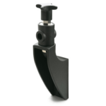
Glass-fibre reinforced technopolymer clamping knob, black colour, matte finish, with nickel-plated brass hexagonal end for clamping by means of a key, threaded hole.

AISI 304 stainless steel screw, nut and washer for the fixing of guide rail cylinder to the bracket.

  • SPR.V-A: with lower lip.
  • SPR.V-B: without lower lip.
General information
Features

Particularly suitable when the angular and linear positioning needs to be executed in two different moments, for example when the distance between the guides has to be set more frequently than the angulation.

Maximum tightening torque for screw assembly 39 Nm.

Accessories
Accessories on request

Spacer for guide rail bracket DSG-A (code 419676) or DSG-B (code 419677) in glass-fibre reinforced technopolymer, black colour, matte finish.

Other executions
Special executions on request

AISI 304 stainless steel guide rail cylinder.

Instructions of use
Assembly instructions
  • Fit the guide rail bracket (Fig. 1).
  • Assemble the guide rail cylinder to the support, with screw, nut and washer (Fig. 2).
  • Insert the washer on the eye screw and assemble the knob (Fig. 3).
  • Insert the eye in the guide rail cylinder housing (Fig. 4).
  • Insert the guide pin in the guide rail cylinder hole. Set its linear and angular position and then clamp the knob (linear positioning) and the fixing nut of guide rail cylinder (angular positioning) (Fig. 5).
Handlekurv
Skroll til toppen