

Velg deltype
Velg ønsket deltype for å se forhåndsvist tegning av tekniske dimensjoner
Bracket Material
Material
Bushing Material
Carrying Capacity
Diameter
Plunger Diameter
Type Of Assembly
Type Of Tube
Diameter Bases
Connecting Thread
External Diameter
Handle
Hole
Lever Length
Wheel Base
Threaded Screw
Hole Distance
Threaded Connection
Type Of Bellow
Type Of Vacuum Cups Holder
Vacuum Cup Holders Dimension
Vacuum Cups Dimension
Connector
Main specifications
Material
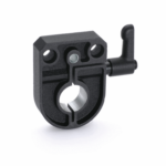
Die cast zinc alloy, epoxy resin coating, black colour, matte finish.
General information
Features and applications
BSA51 locking bases allow an easy and quick locking of the spindles after their positioning. They are equipped with a Ø 6.1 mm hole to fit the referring pin of the indicator. They can be assembled with the handle either on the right or on the left and can be fitted to the machine by means of two M4 cylindrica-head screws (not included in the supply).
Type GN 302 adjustable handle with die-cast zinc alloy lever body and AISI 304 stainless steel clamping element.