BSA51

Direct drive Indicators

Teknisk datablad
CE.25201-pa01_pa02_pa05

Viser alle 4 resultater

    Description BSA51-8
    B
    —
    • —
    L
    —
    • —
    f
    —
    • —
    f1
    —
    • —
    l1
    —
    • —
    l2
    —
    • —
    d
    —
    • —
    d1
    —
    • —
    Weight
    —
    • —
    CAD
  • Description BSA51-8
    B 33
    L 47
    f 21
    f1 23.5
    l1 30.5
    l2 11
    d 8
    d1 4.5
    Weight 84
  • Description BSA51-10
    B 33
    L 47
    f 21
    f1 23.5
    l1 30.5
    l2 11
    d 10
    d1 4.5
    Weight 83
  • Description BSA51-12
    B 33
    L 47
    f 21
    f1 23.5
    l1 30.5
    l2 11
    d 12
    d1 4.5
    Weight 82
  • Description BSA51-14
    B 33
    L 47
    f 21
    f1 23.5
    l1 30.5
    l2 11
    d 14
    d1 4.5
    Weight 81
Main specifications
Material

Die cast zinc alloy, epoxy resin coating, black colour, matte finish.

General information
Features and applications

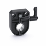
BSA51 locking bases allow an easy and quick locking of the spindles after their positioning. They are equipped with a Ø 6.1 mm hole to fit the referring pin of the indicator. They can be assembled with the handle either on the right or on the left and can be fitted to the machine by means of two M4 cylindrica-head screws (not included in the supply).

Type GN 302 adjustable handle with die-cast zinc alloy lever body and AISI 304 stainless steel clamping element.

Handlekurv
Skroll til toppen