

Main specifications
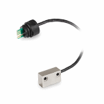
Sensor
Die-cast zinc alloy nickel-plated body
Cable
Shielded cable with black PVC sheath Ø 3.5 mm, bending radius when moving ≥ 34 mm.
Connector (IP67 protection)
Glass-fibre reinforced polyamide based (PA) technopolymer, black colour, matte finish.
NBR rubber O-Ring.
General information
Features and applications
Snap assembly that facilitates insertion and guarantees correct connection even in the presence of vibrations or accidental tears.
Other executions
Special executions on request
Magnetic sensor with cable of different lengths (max. 5 m).
Instructions of use
Assembly instructions
- Insert the connector in the appropriate seat of the magnetic measuring system MPI-R10, and push it in until it clicks (Fig.1).
- Fix the magnetic sensor by using M3 screws (not included in the supply). Distance between sensor and magnetic band to ensure a correct reading of the displacement: max 1 mm.
Disassembly instructions
The connector can be removed simply by pulling with your fingers, gripping the appropriate notches. If necessary, use a slotted screwdriver to lever in the housing shown in Fig.2.