
Polyamide-based (PA) technopolymer, grey colour.
Packing rings
- TPE flat gasket (HFL-EF).
- NBR synthetic rubber O-Ring (HFL-ER).
Connector with sensor block
Right side output including protection against water sprays (protection class IP 65 according to EN 60529).
For a correct assembly see Warnings.
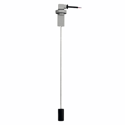
Dipstick
AISI 304 stainless steel tube, fastened to the body by a nickel-plated brass coupler.
Float
NBR synthetic rubber.
Standard executions
- HFL-EF: assembly by means of a flange with 3 holes at 120° for 3 zinc-plated steel screws with hexagon socket, supplied. It can be assembled also with 2 holes at 180°.
- HFL-ER: assembly by means of a 1" Gas threaded coupler.
Maximum continuous working temperature
80° C.
HFL-E rapid levels show a minimum or maximum default level, according to the application needs.
Highly versatile, these rapid levels allow to define the most accurate set point by simply disassembling the dipstick float and cutting the dipstick exactly where needed, according to the specifications shown in the table.
Free from magnetic parts, the float is integral to the dipstick making this level indicator ideal for use in tanks containing dirty liquids, water, oil, coolant oil, also with iron metal parts or foams. Moreover, the operation is independent of the fluid electrical conductivity.
To ensure utmost safety, the electrical components are separated from the tank and perfectly sealed by means of ultrasound welding.
| Table for cutting dipstick | |
|---|---|
Control quote L = (mm) | Dipstick cut quote for minimum level A = (mm) |
| 120 | 116 |
| 140 | 137 |
| 160 | 158 |
| 180 | 179 |
| 200 | 200 |
| 220 | 221 |
| 240 | 242 |
| 260 | 263 |
| 280 | 284 |
| 300 | 305 |
| 320 | 326 |
| 340 | 347 |
| 360 | 368 |
| 380 | 389 |
| 400 | 410 |
| 420 | 431 |
| 440 | 452 |
| 460 | 473 |
| 480 | 494 |
| 500 | 515 |
HFL-NO: the electrical contact opens when the liquid reaches the desired intervention level.
HFL-NC: the electrical contact closes when the liquid reaches the desired intervention level.
| Electrical features | |
|---|---|
| Power supply | AC/DC |
| Electric contacts | NO normally open NC normally closed |
| Maximum commutable voltage | 230 Vdc, 230 Vac |
| Maximum current | 3 A |
| Commutable power | 60 W 60 VA |
| Cable gland | Pg 9 / Pg 11 UNIFIED |
| Conductors cross-section | Max. 1.5 mm2 |
- Level indicators in different materials for use with particularly aggressive fluids and/or maximum working temperature up to 120°C.
- Dipsticks in different lengths and/or in AISI 316 stainless steel.
- Float with through holes to allow positioning according to different needs, avoiding cutting the dipstick.
- Double dipstick and double float manufactured for double minimum and maximum level reading.
- Remove the connectors from the indicator by unscrewing the set screw placed in the bottom, take the contact holders out and loosen the cable glands.
- Slip on the two-pole cable into the connectors (standard connectors) and connect the wires to the terminals nr. 1 and nr. 2 of the relative contact holders.
- Assemble by pressing the contact holders into the relative connectors in the required position.
- Screw the connectors to the indicator and then tighten the cable glands.